A node connector
A faceted surface has to be connected together and supported at the right location in space. This requires connectors. Node connectors are the most common way to do this, but they can be complicated because many panels come together at one point. Each panel requires a flat surface on the connector. Rotating the surface in multiple dimensions is complex.
One way to manufacture the complicated surfaces is by 3D printing the connector. In some cases, a design can be milled on a 3D router.
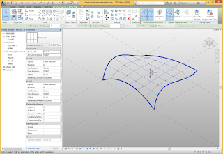
The first step is to make a test surface. In the first variation, the connector will be a cylinder oriented to the surface with four flat surfaces for panels.
Apply a divided surface to it. For this first version, use a Rectangle pattern.
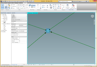
Create a New Family Generic Model Adaptive. Create five reference points with the first one in the center. The first one will locate the node, while the other four will connect to adjacent nodes to determine the surface angles.
Make the five points adaptive.
Zoom in on the Adaptive point 1. Set the Work Plane to be the horizontal plane. Make sure that Draw on Work Plane is selected. Draw a circle centered on this point.
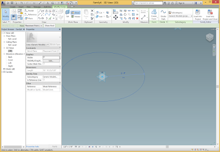
Add a parameter to the radius of the circle. This can be a Type parameter so that it is easy to resize all of the connectors.
Flex the circle by changing the value of the parameter.
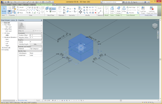
Select the circle and Create Form to make a cylinder. Lock the profiles and give it a Positive Offset value and a Negative Offset value.

The next step is to make void objects for cutting away shelves from the cylinder. To make it easier to see, I hid the cylinder while I worked on the next steps.
Draw Reference lines between the center point and the surrounding perimeter points.
Host a Reference Point on each of the radial arms.
Select a Reference Point and change its Measurement Type to Segment Length. Associate the property with a parameter and call it notch placement. This will determine the inner edge of the notch for a panel in the central cylindrical node.
Repeat this for each of the hosted points. You may have to change between End and Beginning values for the hosted points.
Draw lines between the hosted points. This will be an edge for extruding.
Draw additional lines to define a triangle where the panel will be. Select them, Create Form, Lock the profiles.
Repeat this step for the other panel shelves.
Unhide the cylinder.
Select all of the panel shelves and make them into void forms.
Use the cut command to subtract the void objects from the cylinder.
Flex the model by dragging the adaptive points around.
Load the element into the test surface and place it on five nodes.
Use the Repeat command to propagate it across the surface.
This is an interesting connector but not quite what I had in mind. I would like the cylinder to be more pronounced. Making the cylinder a little bigger will also give better surfaces for the panels.
Go back to the connector and Tab and click repeated to select the cylinder. Change its height.
Reload. This is better.
This does not work very well. It fails when repeated across the surface. Probably the rectangle pattern was a dumb choice. The cylinders would be easier to build if they were all vertically oriented. The funny little “walls” between surfaces are interesting, but not quite intentional. However, this could be 3D printed and it should work.
Let’s try some new ideas.
If we make it with a CNC 3 axis router, it might be faster and cheaper to manufacture. Making connector have a square base would facilitate manufacturing a lot of connectors and sawing them apart. Eliminating the ridges and walls would lead to less breakage.
Get out a new Generic Model Adaptive. This will be a connector for a hexagonal surface. Make a center node point surrounded by 6 vertex points.
Make them adaptive. Make sure the central one is Adaptive Point 1 and the surrounding ones are numbered clockwise.
Set the Adaptive Point 1 to Orients to Global (xyz). This will assure that its coordinate system always aligns with the Project file into which it is inserted. Mostly, we want the z axis to always go up.
Set the horizontal plane of the Adaptive Point 1 to be the work plane. Draw a Polygon by edge centered on the Adaptive Point 1 with 4 sides. This is just a fast way to draw a square.
Draw dimensions from the edge to the center plane to the edge, in both directions. Draw dimensions from the edge to the edge.
Set the dimension strings to be EQ to make the square centered on the Adaptive Point 1. Label the overall dimension lines with a new parameter called size.
Select the square and Create Form to make an extrusion. Make sure that the profiles are locked, and set the Positive Offset to be 1” and the Negative Offset to be 1”.
Load this into a test surface. I made a divided surface with a hexagon pattern and placed this connector on a node with its six “arms” going out to other nodes. Use the Repeat command to propagate it across the surface. It will be necessary to place it several times, as the pattern of seven points forces propagation to be limited to sets of seven points.
Is interesting to observe that the hexagon pattern has two orientations. The pattern can change orientation based on the curvature of the surface. When it changes orientation, a node can end up with either five or seven panels. This may be attractive, or it may be annoying. If one wants to accept the three conditions (five panels, six panels, or seven panels), then must build the three connectors.
If one wants to enforce the six panels, it is possible to embed the connector inside a Curtain panel pattern-based. Create a new point in the center of the panel and place the connector there.
A triangle pattern works better. The six panel connector can be placed on a surface divided with the triangle pattern to create a regular pattern.
To complete the connector with surfaces, a method similar to the earlier one can be used. However, a small improvement will make a connector that can be easily milled. By subtracting the entire top of the connector, the drill bit can cut the proper faces.
This can be done by making the void objects with the blend tool instead of the extrusion.
Set the work plane to be the horizontal plane of Adaptive Point 1. Since this point Orients to Global (xyz) this new reference point will move up vertically. Make sure that Draw on work plane is selected and place a reference point. Offset it some reasonable amount (6”?).
Repeat with the other six points. Orient them by
Insert (xyz) to make z the surface normal.
Draw the lower chains and the upper chains for the triangles.
Pick each pair of chained lines and Create Form to make void objects.
Cut the solid connector with the void planes.
Test it by dragging the adaptive points around.
Reload into the test surface.
You could place a void cylinder to have the CNC machine drill the connector.


