A strut
Many assemblies require struts or mullions. Straight mullions are easy. One can make and adaptive component with the profile. One can create a mullion in the curtain panel pattern-based family. Spline mullions are only slightly more difficult. The ribbon idea can be used to make a spline curve mullion,.
Radius pipe
 However, bending steel to a spline is difficult, while bending steel to a radius is common. A pipe that approximates a spline by using a series of radial bends would be easy to make and very elegant.
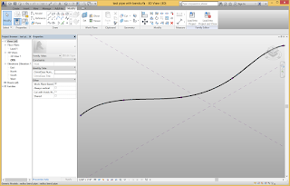
To explore this, create a conceptual mass object. Draw a spline curve with six points. Make a spline through points through the six points.
The spline can be approximated more accurately by increasing the number of radial bends. Good results come from twice as many control points for the radius curves than were used for the spline.


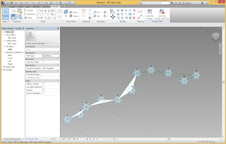
Create a New Family --> Generic Model Adaptive.

Create 11 points, and make them adaptive.
Draw triangles between each sequential set of three points.


Load this into the test model.
Before placing it, select the curve and choose the Divide line command. Set the divisions to be 11.
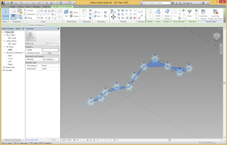
Now place the adaptive curve onto the test curve, snapping to the nodes along the curve.
As long as the spline curve is fairly gentle, the bent pipe fits well. If the fit is not good enough, increase the number of arcs.
There are a few simple refinements. One, it would be good to have actually pipe or rods shown. Two, it would be good to hide the triangles. Three, it would be good to report the radius and chord length of each arc.
Back in the pipe family, change all of the arcs into reference lines. Place a point on the first arc (it does not matter where). Use Set Work Plane and click on this new point to set a plane orthogonal to the arc. Draw a circle with ½” diameter.
Select the circle and the arc and Create Form to make a pipe. Repeat this for the other segments.
Load into the test family and make sure it works.
Back in the pipe family, select all of the triangle forms. Change their visibility to unchecked. It seems like nothing happens, but the visibility will change in anything that the family is loaded into.
Finally, we want to get dimensions of each pipe arc. Switch back to the pipe family.
For each arc segment, draw dimension lines for the arc and the chord. First, set the work plane to be the triangle form. Then use the Radial dimension line to select the arc and place the dimension. By using the work plane of the triangle surface, the arc radius will be measured correctly even when the arc is twisted out of plane. Then, use the aligned dimension to measure the length between the beginning and end of the arc. Tab though to get the Adaptive Point rather than the vertex of a form. This is the chord of the arc.
Repeat this for each arc.
These are all of the dimensions. However, we would like to make a table of all of the dimensions. Once the object is placed into a Project file, it is possible to generate a “schedule” of all of the arcs and their dimensions. It would be good also to name each pipe for easy identification.
To name them, we must create a parameter for the name. Open up the Family Types and create a new parameter. Make it of type Integer and make it a Shared parameter. If you have not already done so for another exercised, you must make a file for storing shared parameters and a group for parameters. I made a “pipe” group. Name the parameter curveID.
To store and report the dimensions, they must be made into “shared reporting parameters”. Click on the radius dimension of the first arc and add a label. Use Add parameter and make an Instance parameter, checking the Reporting parameter box. Make it a Shared parameter. Repeat this for the chord dimension.
Repeat the steps to make all of the dimensions shared reporting parameters.
If you inspect the Family types dialog, you will see that all of the reporting parameters are grayed out, meaning they are uneditable. This makes sense; they are all controlled by adaptive points so there is no fixed dimension. If the adaptive point moves, then the parameter value changes.
The final step in testing this is to load it into a project file. Use the Revit menu to make a new project file. Load the pipe family into the test family, which is a conceptual mass object. Load the conceptual mass into the project file. You can place either the conceptual mass family or the pipe family. Experiment to see what happens. If the change between the two segments is small, it works pretty well. Small diameter pipe works better too.
There are sometimes strange things that happen when the geometry gets twisted.
From the View menu, choose the Schedules command. In the New schedule dialog, choose the Generic Models category.
Add the curveID, the chord parameters, and the radius parameters to the schedule.
The schedule shows the data for manufacturing.
If you select each curve, you can add a number for the chordID. It will appear in the schedule.
This should work for a curve that is all in one plane. For a curve in multiple planes, one would need to measure how much to twist the pipe before each bend. One could put an angular dimension between adjacent triangle planes.
No comments:
Post a Comment