Nine-point patch
A smoothly curved surface is very difficult to manufacture. However, forms can be built and elements cast into them; epoxy, concrete, molten metals and other liquids can harden into almost any shape. Revit can be used to model these elements and then convert them into STL files that can drive machines to make the molds.The key idea is the nine-point patch, as illustrated in Zach Kron’s post on Buildz:
http://buildz.blogspot.com/2012/05/repeat-and-divide-prt-i-curved-panels.html
It starts with a test surface and a Generic Model Adaptive. Save the file as nine-point patch.
Create nine points in a grid pattern. Select them all and make them adaptive.

Next, rotate your view so it is easy to select points 1, 2, 3. After selecting them, make a Spline through points with them. Repeat to make points 4, 5, 6 into a spline and points 7, 8, 9 into a spline.
Pick the three lines and make them into Reference lines.

Drag the points around to watch the splines flex and turn.

Select all three lines and choose the Create form tool. This makes the basic nine-point patch.

Load it into a test surface with a rectangle pattern divided surface. Place it on a 3x3 rectangle of nodes. Select the patch and use the repeat command to propagate it across the surface.


 The patch can be elaborated into a surface with thickness by offsetting each point and constructing a closed loop profile instead of the simple lines.
Go back to the nine-point patch and save it as nine-point patch with thickness. Delete the form. Delete the reference lines.


Repeat these steps with each Adaptive point.
Select all of the Reference points. An easy way to do this is to drag across the entire drawing to select everything. Then use the filter tool to select only the Reference points, filtering out the Adaptive points.


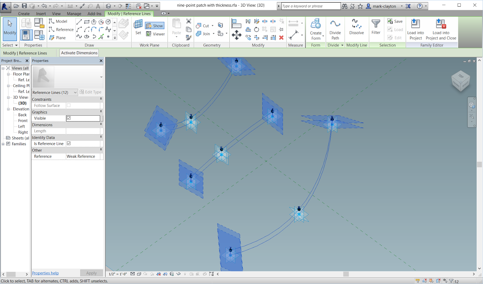
Use the Associate parameter button on the Offset Property to connect all of the Reference points to a thickness parameter.
Play with the value of the thickness to make it move up and down.

Use the Spline through point tool to draw a line segment from an adaptive point to the reference point directly above it. Draw a spline through point through the top three reference points of the profile. Draw another Spline through point through the other vertical edge. Draw a fourth spline through point through the bottom edge of the profile.

Repeat this with the three profile lines.
Draw Spline through points above each of the existing spline profiles, making sure that it passes through the floating points. This should create three profiles that are closed loops.
If everything is good, you should be able to select a chain of four lines for each of the three profile loops. Select all three and Create form to make a new patch with thickness.
Test it by dragging around the Adaptive points.
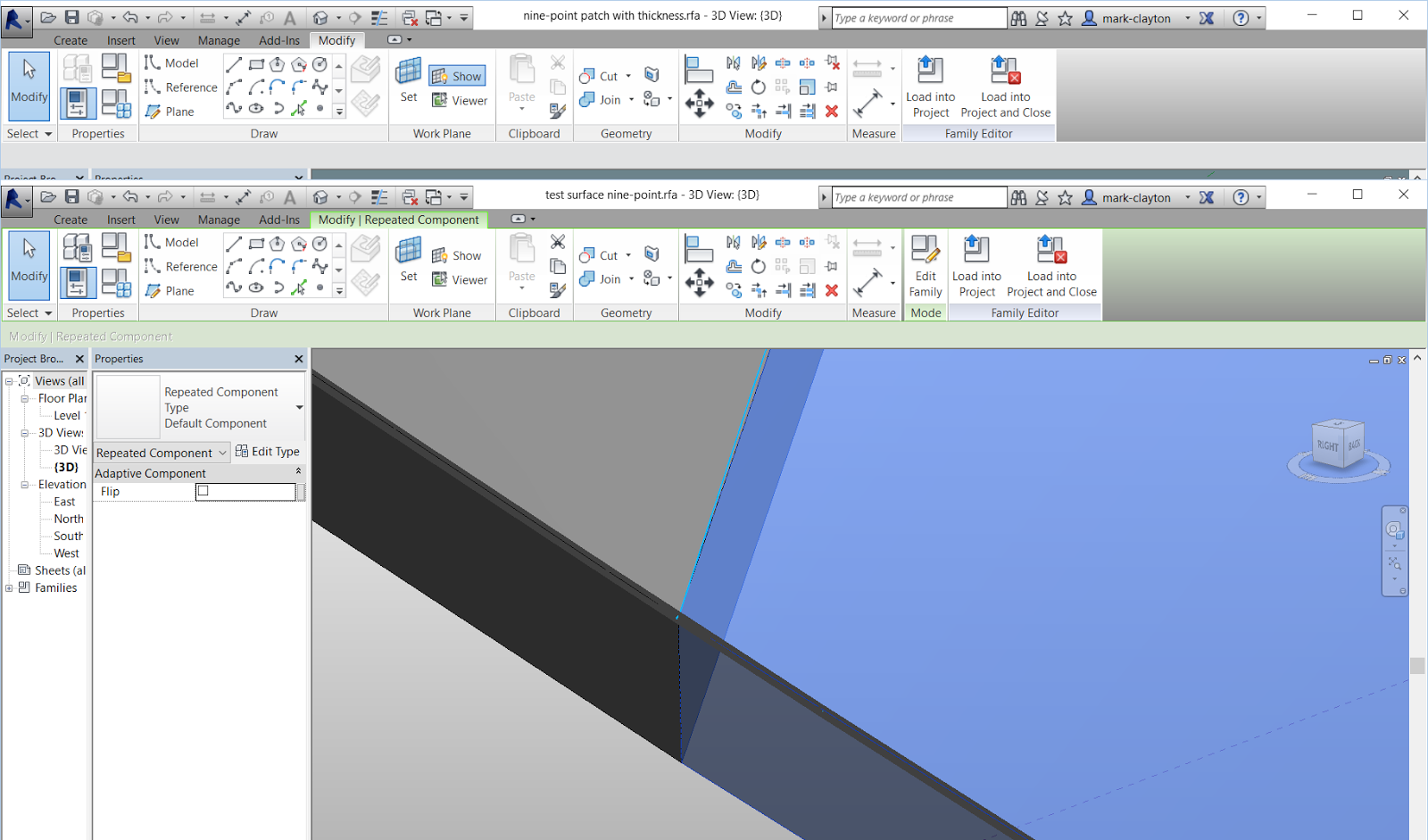
Load it into your test surface.
If it does not work correctly, it may be because the Adaptive points are set to orient in the wrong direction. Make sure that all Adaptive points are set to Orient to Host (xyz). This assure that they use the surface tangent plane as their dominant orientation.

A nine-point block can be used for CNC cutting a surface. The idea is to have a nine-point patch on the top and a squared off block on the bottom. The technique is similar to the striated form tutorial. Two divided surfaces are used to control the top and bottom of the block. To keep the edges vertical, the divided surfaces have their U and V grids turned off and reference planes are used as Intersects to create the nodes. The block objects can be imported into AutoCAD and unioned into a single big solid, or each block can be cut individually and assembled.


As this was modeled, the block could be curved on the top and on the bottom.

However, by using a flat divided surface on the bottom, I constrained the bottom nine points to be on a flat surface.
To make all of the nodes line up vertically, I turned off the U grid and the V grid in the divided surface and used intersects. I did this on both the curved top surface and the flat bottom surface.
No comments:
Post a Comment