A shingle
A shingle model is largely the same as the brick. It must be tilted out of plane so that the shingles overlap the lower shingles.
Start with a test surface. Divide it using the ½ Step pattern.

Get a New family of type Generic Model. Using the Ref. Level view, draw a vertical reference plane on either side of the vertical origin plane. Draw a horizontal reference plane above the horizontal origin plane.
Add dimensions to constrain the two new vertical lines to be EQ dimension on either side of the centerline, and a dimension to specify the distance between the outer vertical lines. Add a dimension for the horizontal line.
Label the horizontal one as width.

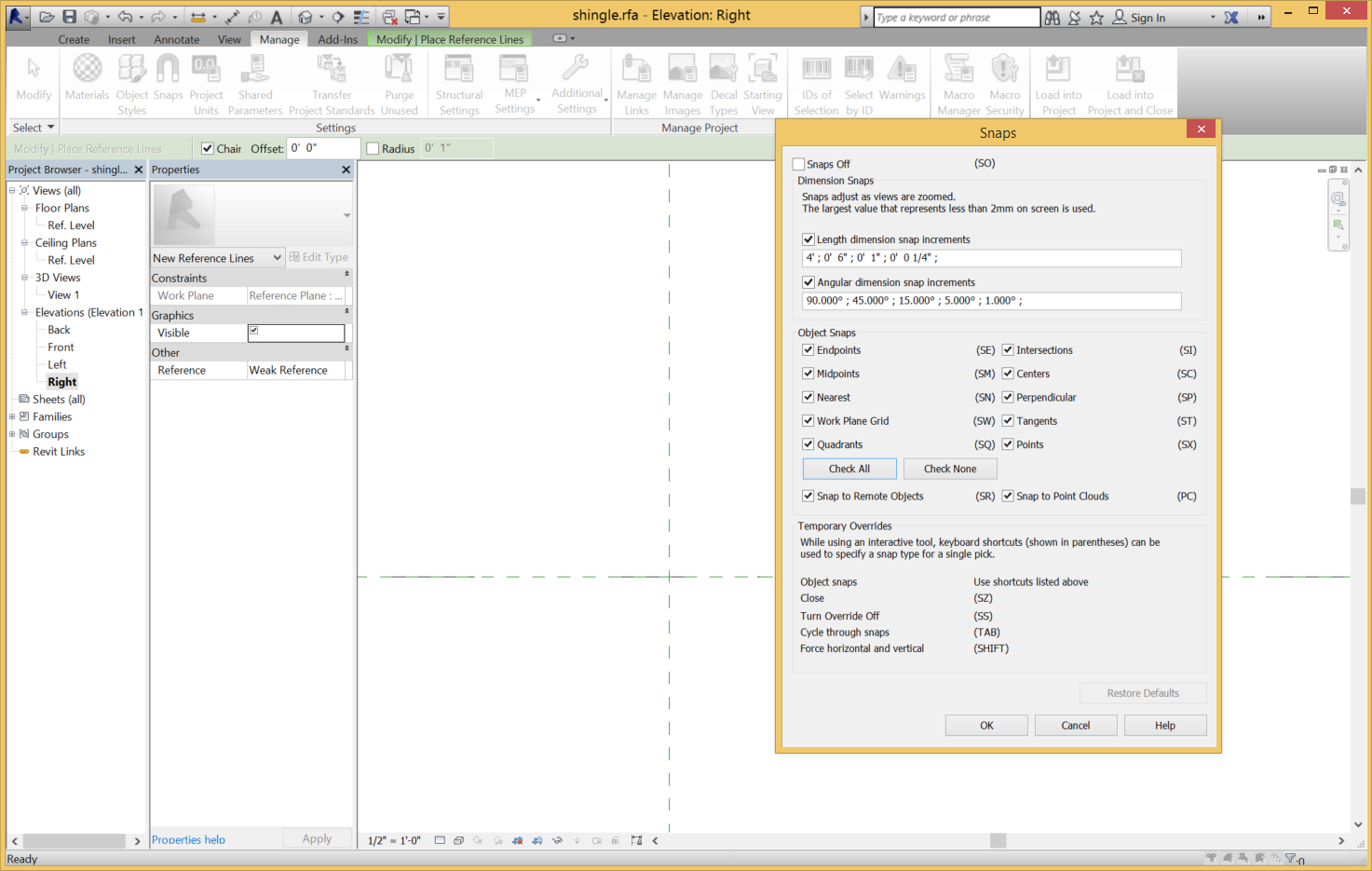
Switch to the Right view to specify the angle of the shingle. Make sure that snaps are turned on.
Draw a Reference Line (it must be a Line!) from the origin out and across the top edge of the shingle.
Annotate it with an angular dimension.
Label the angular dimension and add a New parameter for slope. Test it to make sure that the reference line rotates around the origin.

The next step is to set the work plane to be aligned with the sloped line. Use Set in the Work Plane panel. Tab to get the plane coming directly out of the screen. When you select that view, a dialog will require you to change the view to something that actually shows the new work plane. Choose the Floor plan.
Draw a rectangle extrusion. Lock its sides and align the bottom edge to the reference plane. Add a dimension to the vertical width and label it with a parameter named length.
Change the Extrusion End to ¼” Associate a parameter to this property and call it thickness.

Test it by opening the Family Types dialog and changing the parameter values.
 Open the Family Category and Parameters dialog and make sure that the Always vertical is unchecked and that Work Plane-based is checked.
Close the dialog and save the file.
 Get a New Family of a Curtain Panel Pattern-Based. Change it to a ½ Step pattern, and make the spacing 1’. Change the scale and zoom in appropriately. Save this as Shingle pattern.
Load the shingle family into the shingle pattern family. Pull the Adaptive point 2 up so that it is out of the reference plane. This is a step that helps to disambiguate which plane is active.

Set the Work Plane to be the horizontal plane of Adaptive Point 2. Set the Placement to be Place on Work Plane. Place the shingle on Adaptive Point 2.
Save the family.
Load the Shingle pattern family into the Test surface shingle family.

Change the divided surface to be the shingle pattern Type.
Various things can go wrong. If the surface is curves back on itself, the shingle may not hang properly. The spacing of the divided surface and the size of the shingles can be changed to give different appearances. Making various Types of shingles makes it easy to control the shingle dimensions.
Shingles could be varied in shape, size and color to get different effects.


No comments:
Post a Comment