Friday, November 23, 2012

Screen captures and movie editing

There are many reasons to want to capture the interaction on a computer screen. My motive is usually one of the following:
  1. Show a colleague how to use commands in some software system
  2. Demonstrate new software
  3. Create a user manual for new software
There are commercial packages for doing this, but I have used Windows Media Encoder for several years. It works well and it is free. It can be downloaded from:

It appears that the software is being replaced by Windows Expression Encoder, but I have not yet used that software. It can be downloaded for free at:

One can also purchase a program such as Camtasia. 

The challenge of any of these is the large number of settings and options. You must specify the source (which could be the screen or an external device). This post is focused on capturing the screen, in which case one must specify whether you want the entire screen, a window, or a region of the screen. Having set the input, one must also set the output, which is determined by how you expect to distribute your video. Since video files can be huge, you must be aware of the expected file size and the video coding and decoding (codec). If you are distributing by email, you must use high compression and small size to produce a small file. If you are downloading from the Web, you may also be restricted on file size. If you are streaming, then file size may not be an issue. If you ultimately want to create a DVD or VHS tape, you may wish to capture to that size and compression. 

Here are some settings that have worked well for me in making informal videos for demonstrating software techniques distributed as downloads and played back on screen. First is the About dialog so you can see exactly what version I am using.
Figure 1: Windows Media Encoder.

The first step is to set the Source. In Figure 2 you can see that I have set it for Video Screen Capture. From the Configure button, I set it to capture a region of the screen. One can also set it capture a particular software window, such as the Revit Window. 
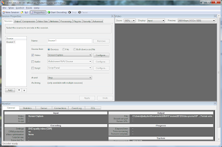
Figure 2. Source settings.
Figure 3. Window selection method. 
The output setting permits one to save the capture to a designated file. Beware that you may have to change the filename for each segment that you create. 

The Compression settings are complicated, but these setting shave worked for me. The DVD quality seems adequate for demonstrations, although I am sure there are higher quality settings. A concern is that I do not know who is going to watch my video so I have chosen a format that should be widely supported. 

Figure 4. Compression settings.

Figure 5. Compression settings. 

Cropping and resizing can be useful, but you can ignore this Property and the others.


Figure 6. Video Size properties. 
To start capturing the video, just click the button for Start Encoding. To stop the capture, go to the task bar and open the dialog to stop. 

I use another free software package for editing videos. You can download Microsoft Windows Live Movie Maker  from 

Figure 7. Windows Movie Maker.
With this software, you can combine multiple clips of screen capture, live video captures, still images, audio and other components into a movie. It uses a simple timeline or film editing view to insert, splice, cut, and rearrange clips.  (Any screen demonstration is better with a little Phillip Glass accompaniment. ;-)

It is easy to record a voice overlay using the Sound Recorder that is available as a standard Windows Accessory. Of course you will need a microphone. 

Note that may programs can produce video that can be used in Movie Maker. You can add animation and transitions to a PowerPoint slideshow, dub a voice over it, and then save the whole thing as a video. Then you can use that as a segment in Movie Maker in combination with some screen captures. A few head shots or live action shots with a video camera or camera phone adds some humanity to it. Even add some Xtra Normal cartoons. The process is fun (at least at first) and results in carefully controlled presentations that can get your point across very effectively.


Monday, July 23, 2012

BIM Triangular panel with filleted hole


 The goal is to make a panel that will fit into a flat triangular mesh that has a hole with graceful fillets at each corner. The first step is to draw it and try to figure out the geometry. From the sketch, the realization that bisecting each angle will provide the centerpoint for the fillets, but finding points to control the curves is pretty complex. Revit demands the use of spline-trhough-points, so an arc won’t work well. The spline-through-point would be prettier anyway for making the fillets.

Make some sketches first to figure out the shape and the geometry.  
Bisecting the angle is a bit challenging. My method is to set points of a known dimension from the vertex along the edge of the triangle reference line.

Connecting the points on the edges adjacent to a vertex will draw a line whose midpoint bisects the angle. Next, if I consider the known dimension to be the length of the hypotenuse of a right triangle, I can use trigonometry to calculate the length that midpoint is from the edge. I can use the same technique to then calculate the location of a point on the edge that defines a line perpendicular to the edge that also goes through the midpoint. Along this line I can measure a given amount to define the width of the strut that goes along the edge of the triangle. 

 The strategy in Revit is to create a rigging for constructing the hole by using reporting parameters for the angles of the triangle, a few given dimensions, and trigonometric equations to calculate the values of other parameters. Because I have chosen to use some given dimensions, this panel will probably be brittle and break as the dimension become extreme. If I build it for a particular dimension, it will probably work as long as the dimension does not change too much. In addition, if the panel does break, I may be able to change the given dimensions to get it to work again.

 In Revit, start with a new family based on a Curtain Panel Pattern-based. Select the grid outer edge, and use the Type selector to change it to a Traingle (flat). You can pull the points up and down to see the triangle deflect in space. 


Create three parameters for angles (a, b, c), and make them Instance, Reporting Parameters. Create three more parameters for the half-angles (the angular dimension of the bisected angle). Calculate these parameters using formulas.

With the triangle displaced in space, draw angular dimensions between each two sides. It is important that you dimension between the reference lines as they are controlled by the adaptive points and can move freely in space. Label these dimensions with the angle reporting parameters. 


Label the angular dimensions with the reporting parameters that you created. 


It can be convenient to select rapidly the plane defined by the three vertices of the triangle. You can create a surface by picking the three edges and clicking on the Create Form icon. Make just the surface and not an extrusion. 


 Lift the adaptive points of the vertices and spin the 3D view to verify that the angular dimensions remain in the plane of the triangle, whatever angle results from the changes to the vertices.


The next step is to draw reference lines from each vertex toward the middle of the triangle to bisect the angles.

While it seems like one could place angular dimensions between the edge and the bisecting line and constrain it dimensionally to bisect the angle, I cannot get that to work. I had to choose a different method.


Create a parameter to control the displacement of the point from the vertex of the angle. I called the parameter “fillet_center” and gave it a default value of 2’ 0".


Considering the first angle, place points on each adjacent edge. Draw a reference line connecting the two points. 


Continue the same process for the other two angles.


Click on the point and set its Measurement Type property to be Segment Length. Associate the fillet_center parameter with the location of the point, being careful to measure from the vertex by watching the blue arrows.
If you accidently set the Segment Length when the blue arrows are indicating the wrong direction, it seems best to set the association of the value to of the Segment Length to none, and then associate the value to the fillet_center parameter again with the proper direction. 


Continue around the triangle, constructing the reference lines to span across from the two edges. Since the offsets from the vertex are the same length, the small triangles at each vertex are now isosceles triangles.


The midpoint of the spanning line will be on the line that bisects the angle.

 Reconnect the reference lines through the vertices to the midpoint to bisect the angles.
Spin the model around and pull the adaptive points up and down to make sure everything stays on the plane and the points and lines adapt as they should.


The next step is to calculate the length along the edge of the triangle that locates a line through the midpoint that is perpendicular to the edge. This line will allow us to measure the thickness of the strut and the endpoint of a curve that defines the fillet. 

 Add some points on the edges of the triangle and make a parameter for them.


First, calculate the length from the midpoint of the base of the isosceles triangle along the base to the edge. By the definition of sine, the opposite edge equals the sin(phi) * hypotenuse. I created a parameter to hold this value. Then I used this value to calculate another right angle length and determined an offset from the vertex of the angle. Constructing a line from this point back to the midpoint gives a perpendicular to the edge through the midpoint. 


 Place a point hosted on this perpendicular line allows one to position with Segment Length a width of the strut.


A final control point determines the arc of the spline that defines the fillet. This point must simply be on the bisecting line. I used a parameter to determine how far the point is from the vertex. 


Repeat this process to make six strut widths and three control points for the fillets. Test the rig by moving the adaptive points up and down. 


 It is probably helpful to see all of the formulas for locating the reference points.
 Draw the profile of the hole and extrude it. Make sure that the extrusion is locked top and bottom, and then offset it up and down from the plane that defines the profile.


Extrude the face that defines the panel. Make the hole into a void object and use it to cut the panel. 


 Some experimentation showed me that the filleting does not work very well. My strategy is to make the location of the fillet control point vary by the dimensions of the triangle. I created a new parameter and used it as a factor to adjust the location of the fillets.

Test it by loading it into a family or project and applying it to a surface.This works better.

 The final formulas are shown.
I like this panel. It could still be refined further, but its proportions seem elegant and it adapts well to the surface.