Key to manufacturing curved surfaces that have been designed to be faceted is to lay out the facets on a single flat play for cutting, a process simply called “flattening” or “unfolding” or “developing”. The flattened arrangement can be arranged on a piece of panel stock and cut with a laser cutter, CNC router, CNC plasma cutter or other CNC equipment.

Typically flattening is done with AutoCAD (shown in my post from 8/Aug/2013, Fabricating Revit models: laser cutters) or Rhino’s Unrollsurf or Smash command. Here is a way to do it in Revit.
I haven’t had time to describe this, so I will show the process backwards, from the end result to the beginning. This will illustrate the concepts.
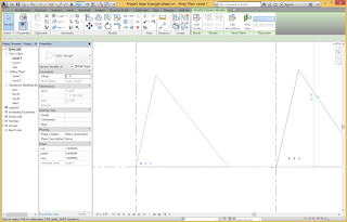
The goal is to produce the facets for a complex surface arranged neatly on a sheet for cutting, with each component numbered. Here is such an arrangement in Revit. To cut this on our laser cutters or CNC machines, I merely Export the Revit view in DWG format and adjust it slightly for layers for sending to the machine. The view is already scaled appropriately for the cutting bed.
The concept is to regenerate the triangles in a separate file and lay them out neatly. A label object automatically provides the ID in panel, row, and column by getting values from parameters in each object.
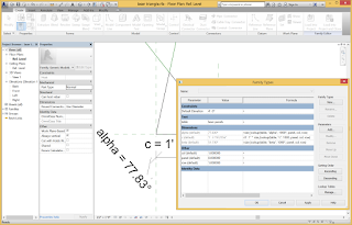
The method is to generate the triangles using a Lookup table, which is basically a spreadsheet from Excel, describing the parameter values for all of the triangles. The flattened triangle is a family of category Generic Model that accesses the lookup table. Getting a triangle to configure properly given the two angles and side length was tricky, but eventually it fell into place.

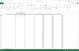
The lookup table must follow a very specific set of rules for its formatting. Each component is a record in a flat file database and is listed in a row, where each column describes a field. The first row is ignored, but can contain a test description of the item. The columns must have headers with a special syntax. The first part of the header is an identifier, the second part is the type of data (usually NUMBER), and the third part is the units, such as FEET or INCHES. These parts are separated by the special symbol ##. The table must be saved as a CSV file and then loaded into the family using the Manage Tables function.

When the Revit family accesses the table (I have stored the name of the table in a parameter “table”) it uses the size_lookup() function. The first argument is the name of the table. The second argument is a text string that matches the column in the table that contains the value to return. The third argument is a default value to return if the lookup action fails. The final columns contain values to look up in the table beginning in the second column of the table and moving sequentially across columns. In this example, the function looks for a match in the three columns of “panel”, “col”, and “row”.
The lookup table was generated from the Revit model of the triangulated surface. The table is simply a schedule of the Generic Model objects that was saved as a CSV file (txt file extension). Schedules can only be made in Project files, so the project file contains the family that depicts the surface with its triangles. The CSV file was opened in Excel and pasted into the worksheet template.
A curtain panel pattern-based contains the triangles and was applied as a Divided Surface to the form.
The curtain panel pattern-based family uses a triangle pattern. It consists mostly of a triangle facet family that uses shared reporting parameters to collect the data for the schedule.
The system can be used to flatten anything that is planar and that can be parametrized.
We will cut some of these out in the next few days and see what we get.


No comments:
Post a Comment