A brick wall
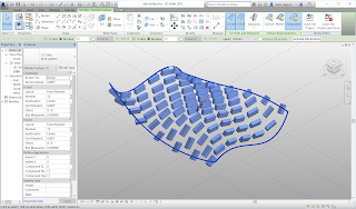
Curtain panel pattern-based can be used to lay brick in offset courses. The key concept in this lesson is that a non-adaptive object can be placed in the pattern-based panel. Thus a standard brick can be used to make a curved wall. There are two examples: 1) the brick that is laid in tilted courses to conform the surface of the bricks closely to the surface, and 2) the brick that is laid in horizontal courses so that its face is always vertical.
The first step is to draw a brick. It might as well be a parametric brick. Create a new family as a Generic Model. Draw the brick with its insertion point aligned with its bottom edge and its face centered. Draw a two vertical planes and one horizontal one.
Add dimensions, making the two vertical planes EQ from the centerline.
Label the dimensions with type parameters for length and width.
Draw an extrusion. Sketch it with a rectangle. Lock the edges of the rectangle to the reference planes.
Finish the extrusion. Select the extrusion and look at the Extrusion End property. Click on the Associate parameter button and give it a new parameter of height.
Look at it in 3D to see if it is right. Adjust the parameter values and change the shape of the brick. Note that you can put equations into the parameter values to calculate things like the height of a brick (=8”/3-3/8”).
Finish up with a brick that is nominally 8/3” high, 8” long, and 4” wide.
In the Category settings, make the family Work plane based and uncheck always vertical.
Save this file as brik.rfa

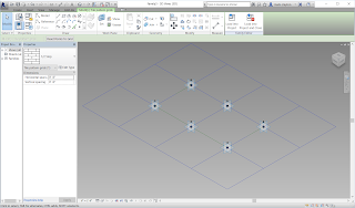
Now start a new family of curtain panel pattern-based. Click on the blue border to change the pattern type. With the type selector, change it to 1/2 step. Change the spacing of the pattern to 8” in each direction. You will want to adjust your zooming and change the scale so it looks better. Drag the points around to get everything out of plane and away from the default work plane. Save this file as brick pattern.rfa
Go back to the brick family and load it into the new pattern.
Before you place the brick, set the work plane to be the horizontal work plane of the middle adaptive point. This will keep the brick oriented and located on the pattern.
Save this.
Create a test surface as a conceptual mass. Load the brick pattern into the test surface. Divide the surface and apply the brick pattern.

The spacing of the nodes may need adjustment. Use 4” in one direction and 8”/3 in the other direction. This should space the mortar properly.
The next idea is that bricks are typically laid in level courses. To test this, make a test surface that is roughly vertical, like a wall. A quick way to do this is to Ctrl drag the level 1 to make two more levels. Then draw a Spline through point on each level. Blend sweep between them to make the surface.
Go to the brick family. Change its Family Category and Parameters to check Always vertical
Load it into the brick pattern. Save the brick pattern with a new name, such as brick pattern vertical.rfa
Change its Family Category and Parameters to check Always vertical.
Swap out the brick for brick vertical.
Load it into the test surface and apply it to a divided surface on the wall.
It looks right, except the bricks are rotated to show their width rather than their face. We could work to try to rotate it, but it is a parametric
brick and it is easy to swap the parameters. Go back to the brick vertical family. Swap the width for height. Change the associated parameter for the Extrusion end too.
Reload into the pattern, and reload into the test surface.
Adjust the spacing of the bricks, once again using Fixed Distance.
The brick wall should look right!


No comments:
Post a Comment