The Buildz blog has an excellent post on tools for checking the curvature of panels in a curved surface . However, I thought there might be
an easier way. I found a method that uses Filters in Visibility graphics and
shared reporting parameters. It is easy to understand and in some ways better.
It does not require a special panel family for reporting the curvature.
Instead, it works with any panel that has curvature.
A panel
To illustrate, start by creating a new curtain panel pattern based family. Use a Rectangular pattern. Pull the adaptive points out of the
default plane. Draw reference lines for the diagonals. Place a point on each
diagonal reference line. Move each point to the midpoint by setting its
Normalized Curve Parameter to 0.5.
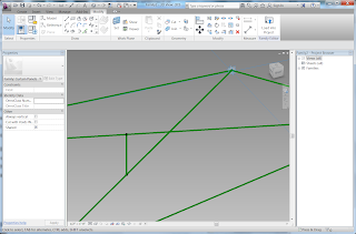
Draw a reference line between the two diagonal midpoints. This will be the measurement for how far out of a plane the panel is.
Set the Workplane to be this measuring line. Add a dimension
between the two midpoints on this workplane.
Make the dimension into a parameter by using the Label tool. Make it an Instance parameter and a reporting parameter. Make it a shared parameter and call it outOfPlane.
That’s the panel. Adding a measurement like this can be done
to any panel. The color will be handled by Visibility Graphics of the view using
Filters.
A curved surface
The next step is to make a curved surface. You can load one
that you have already created or make a new one.
To make a new one, create a new Conceptual Mass. I made some
reference planes to control the profiles of a curved surface. I drew four
curves, one on each reference plane. Activate each reference plane to draw a
reference line using Spline Through Points.
Use the Create Form tool to convert this into a surface.
Dividing the surface
Load the panel into the conceptual mass. Choose the conceptual mass object to select it. Click Divide Surface to make a divided surface. Use the Type Selector to set your panel to be the type.
The conceptual model has all of the information about
curvature of each panel. Once we have inserted it into a Project file, we can
now use the Schedules and Visibility/Graphics with filters to inspect the curvature.
Create a new Project. Load the conceptual mass defining the
surface into the new project.
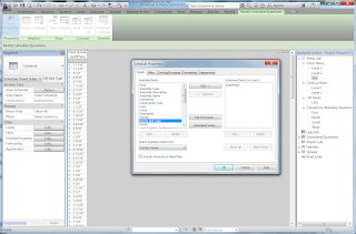
 To inspect the out of plane value for each panel, create a
new schedule. (You may have to make sure that the shared parameter file is
loaded.)
To obtain a color-coded visualization, select a view, such
as the 3D view. Open the Visibility Graphics dialog, and choose the Filters
tab. Create a New filter, and give it an appropriate name.
Check the Curtain Panel for the Categories. In the Filter
Rules, pull down the Filter by: drop down menu and choose More parameters ….
Use the Add parameter button to reach the Parameter
Properties dialog. Set the new parameter to be a shared parameter and choose
your parameter for measuring flatness. Apply the parameter to Curtain Panels
and close the dialog.
In the filter Rules section of the Filters dialog, select
the outOfPlane parameter. Choose the criteria to be “is less that or equal to”
and set the value to be 2”.
Copy this filter a couple of times and set additional filter
rules criteria.
In the Visibility / Graphics dialog, add your new filters.
Change the Projection Surface Patterns for each filter to be
a different color.
My surface is acceptable. I can change the filters to get a
more detailed analysis of the surface. I can change the surface to increase the
curvature or decrease the curvature.
Summary
This method uses a reporting parameter of the panel to retrieve the amount that the panel is out of perfect flatness. This parameter is used by filters in Visibility/Graphics to colorize the surface. It can also be used to create a schedule of all of the panels.In comparison to the method on the buildz blog, this method is very simple and straightforward, requiring no helper objects or duplicate panels. Also, this method can be applied to any panel being designed as a simple reporting parameter. The color coding is done in the project that uses the panel. For greater variation of the color coding, one need only add more filters. The filters only affect one view. Other views may still provide a realistic coloration of the surface. However, one can apply filters in other views by using a template.


Great stuff Dr. Mark! Check out a similar method here: http://buildz.blogspot.com/2012/02/computational-design-lab-reinventing.html
ReplyDeleteBTW, the first ten images in this post are not showing up in my browsers.
Images should be fixed now.
ReplyDeleteZach's extensive tutorial covers filters and schedules very well.