The designs of Palladio have had an important influence on architecture for over four hundred years.

The Villa Rotunda in Vicenza is a masterpiece of Renaissance and Neo-Classical architecture.
Palladian design came to America and influenced architecture throughout the colonies and the states.
The southern plantation houses of my native state of Louisiana were inspired by Palladio. It is interesting to study them as a house type.
In Chalmette, the Beauregard House is one masterpiece.This house near New Orleans is part of a National Historic Park and is open to the public. It is a prototypical design for a plantation house (although not actually associated with a plantation.)
Oak Alley, on the banks of the Mississippi River north of New Orleans is another masterpiece.
Destrehan is another example, older than the other two and not as refined.
A plantation house is a good exercise in the use of constraints to enforce symmetry and proportion.
The first step in a project done with Revit is much like the first step in a project done on paper. Draw the site, using the Massing & Site -> Toposurface tool. Draw a Property Line using the same menu. From the Manage->Project Information, you can describe the client, the location, and, using the Energy Settings parameter, choose a Location Weather and Site value.
For most buildings, the architect knows very early in the process how many stories there are, although the exact height of each story may not be known. Switch to an Elevation view and then use the Home->Level command to draw a Level 1 and Level 2. You can rename the levels and set the heights of the levels after you draw them.
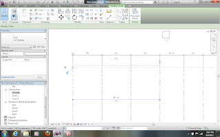
Most real buildings are based on a grid that helps define the structure. A Palladian villa or Louisiana Plantation House typically has a symmetry that is defined by a grid. From a Plan view, use the Home->Grid command to draw lines for the grid.
Symmetry is based on the establishment of centerlines. If you pick the centerline, you will see a dimension line. You can click on the little icon of a dimension line to make the "temporary dimension" into a "permanent dimension. Then, you can set the grid line to have neighboring grid lines that are equally spaced.
You can also draw an aligned dimension line with to locate several reference grid lines, and then set them to be equally spaced by clicking on the EQ icon.
 To make the drawing look tidy, you can drag the dimension lines until the leaders and lines are all aligned.
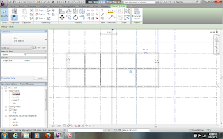
Having draw the grid lines and dimensioned them to control the bay proportions, you can easily draw walls. It is actually best to draw the walls away from the grid lines. Once you have drawn the walls, you can drag them to the dimension line. A lock icon should appear, and you can lock wall to the grid.
This just shows more locking of walls, this time on the Level 1. Notice in the Properties box to the left that the Top Constraint is set to "Up to level: Level 2". The walls on the Ground floor should have a Top Constraint of "Up to level: Level 1". This command sets the height of the wall to the level. If you later change the level in a section or elevation view, the wall will remain constrained to the level above.
This just shows more locking of walls, this time on the Level 1. Notice in the Properties box to the left that the Top Constraint is set to "Up to level: Level 2". The walls on the Ground floor should have a Top Constraint of "Up to level: Level 1". This command sets the height of the wall to the level. If you later change the level in a section or elevation view, the wall will remain constrained to the level above.
Here a roof is being drawn, but the roof has a "Base Level" of Level 1. It should be Level 2. You can change the parameter and the roof will jump up to the right location.
A second roof can be drawn to provide the double pitch that is characteristic of Louisiana plantation.
From the View menu, one can draw a section cut line in a plan view. This does not merely draw the symbol for a section cut, but generates the entire section too.
If you want the section to have walls and floors as a solid fill, you can easily change the View Properties by using the Visibility/Graphics Overrides parameter. Set whichever objects are needed to have a solid fill.
 Draw the interior walls on each level. It is easiest to sort of sketch them in, deliberately avoiding the grid lines. Once they are drawn and trimmed properly, you can drag them to the grid line and then lock them in place to align with the grid line.
On another level, the process is repeated to lock the walls to the grid lines.
The French windows are drawn using a door family. First you must load the Door family from the library. The family defines the basic un-dimensioned form of a French window. You will add the dimensions later.
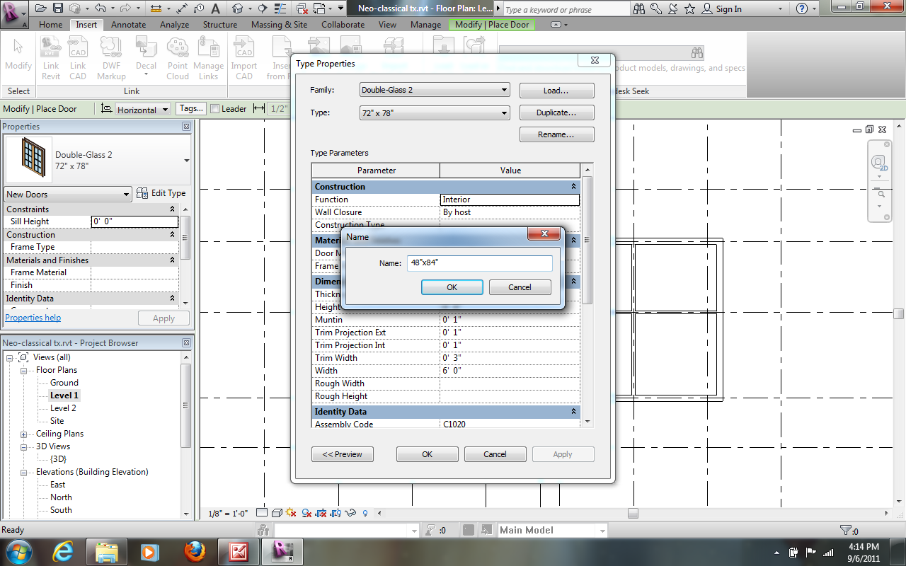
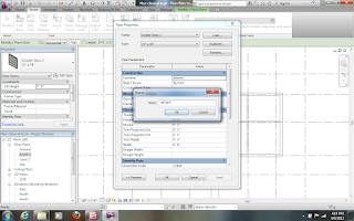 Once the door is loaded, you use the button for Edit Type to define a new door type that you can insert repeatedly. Duplicate the current type and give it an appropriate name.
Having duplicated the type, you can edit the Dimensions, such as the width and height.
You can insert the doors into the walls. Again, the best way is to place them imprecisely. You can then drag them to the right location and use the EQ icon to center them between walls.
If necessary, use the Aligned linear dimension to set the dimensions to be equal.
An entablature can be added with the Beam tool. You can load a timber family and then establish the dimensions of the beam by Edit Type.
From the 3D view, you can see the beam along the outside edge of the roof.
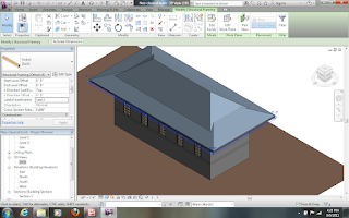 You can edit the "sketch" of the beam to get it aligned with the appropriate part of the roof.
There is a Doric column family in the standard library. Load the family and then add columns around the outside edge. You can use dimensions to lock the columns a distance from the grid lines and align them to grids as centerlines.
Here the dimension is being used to set the end column away from the grid line by 1'2".
The columns by default have a top attachment to the Level 1. You can change the Top Level to the Level 2 and they will stretch to a double height.
The columns also have a Top Offset of -1'4" which places them at the bottom of the beam that represents the entablature. Once you get one right, you can copy them around the building.Or, if you have already placed them, select them all and change their parameters at once.
This is a good time to "flex" the model by moving the grid lines and levels around. If you have properly locked everything to the lines, the house will reshape.
The doors seem too short. You can create a new type of door and quickly change all of the doors to the new type.
As you can see, the elements are heavily constrained to the grid lines.
A porch floor was inserted and shadows were turned on. Now the model can be changed in proportion by simply moving the grid lines.
The basic form of the type is complete and fully constrained. Stairs, railings, chimneys, and other elements can be added and locked to appropriate lines.
Alternative columns could be modeled and quickly substituted. Different door and window families could be collected to allow rapid substitution.
The implications of using constraints and locks to hold a model into a set of relationships is that one can model a building type and then rapidly make instances of the type. The rich formal systems of sameness and variation that make American traditional cities so beautiful can be expressed with BIM tools.


 To make the drawing look tidy, you can drag the dimension lines until the leaders and lines are all aligned.


 Once the door is loaded, you use the button for Edit Type to define a new door type that you can insert repeatedly. Duplicate the current type and give it an appropriate name.


 You can edit the "sketch" of the beam to get it aligned with the appropriate part of the roof.


Merit Casino - Top Rated Online Casinos in the USA
ReplyDeleteMerit Casino Review - The Top Rated Online Casinos in หาเงินออนไลน์ the USA This site 메리트 카지노 고객센터 was developed for players from the United choegocasino States.