A ribbon using adaptive components
 An ancient way of making a curved surface is to use planks. Boats and ships are built by nailing thin planks to bulkheads or ribs.
Modeling this in Revit is fairly easy using an adaptive component that works with the nodes on a surface.
Before one can do this, one must make a surface. Preceding tutorials describe how to do this. Create a divided surface with 6 divisions on the U grid and 6 divisions on the V grid.
Start a new file using Revit.New
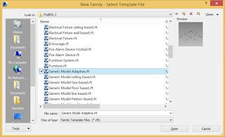
 family. Choose Generic Model Adaptive. This modeling environment looks much like the Conceptual Mass modeling editor, but it has some different tools.
The adaptive elements are very strange. Dimensions are largely meaningless, as they can change when the object is placed. The geometry is controlled by adaptive points that are placed when the user places the component.

Using the point tool, place six points. They can be placed randomly, but I suggest that you put them into more or less a straight line.
Now select the six points and pick the icon for Make adaptive. The points become numbered and show their coordinate systems. These coordinate systems will adapt to the location of the point, and settings on the point. The number of the point corresponds to the placement order of the point when the component is placed. The number can be changed.

Select the six adaptive points and pick the Spline through points tool. You can twist and curve the spline by moving the points around in 3 dimensions.

This line represents the length of the plank. You will sweep a shape along this line. The cross section of the plank must be drawn on a plane perpendicular to the line for sweeping. Use the Set work plane tool and carefully pick the plane on Point 1 that is perpendicular to the sweeping line. You may find it easier to move point 2 so that the plane is more distinct.

To make the adaptive ribbon, select the cross section and then CTRL select the path. You could drag across everything and then use the Filter command to select only the lines. Use the Create form tool to make the 3D solid ribbon.

You can drag the points around and the ribbon adapts. Save the ribbon.
Now it gets fun. Load the ribbon into your surface model. Using Load into project.
Place the ribbon on the six consecutive nodes of the surface.
Select the ribbon on the surface, and pick the Repeat tool. The ribbon gets repeated across the entire surface using six points at a time.

This ribbon isn’t quite right as a plank, but the cross section could be drawn more carefully and better results would occur. However, it should get the idea across.
The quantity of ribbons can be changed simply by changing the U and V grid numbers of the divided surface.

To build something like this, there are many physical constraints. The planks must both bend and twist, so the choice of material, thickness and width is important. Because our node generation was pretty sloppy, the planks might also be curved. There must be adequate ribs to hold the planks in the right location.
Experimentation with physical models may lead to an understanding of these constraints. Revit can be used to calculate the amount of twist and bend in each plank.
To draw the cross section, it is easy to use the Work plane viewer. Draw a narrow rectangle centered on the point 1. Dimension lines can help too. I made the plank cross section .25” x 2”.


No comments:
Post a Comment