Tuesday, October 30, 2018
Test your knowledge of the building code
I am curious what architects and architecture students know about the building code. Test yourself by filling out this form. I will share the results.
Survey of Building Code Analysis Knowledge
Sample files for lecture and SMARTreview APR demonstration and tutorial.
Architectural Quality Conceptual Cost Estimating
At the ARCC conference in Philadelphia last May, I presented a method for cost estimating that I teach to my students. The method is intended to fit into a BIM-based workflow for conceptual design. After sketching a building concept with conceptual masses, conceptual floors, and conceptual walls, the designer assigns quality factors to each building system. Costs for each major building system are obtained from Means Square Foot Cost Data. The Means data also has factors for the percentage cost of each building system in a typical project. The architectural quality cost estimate is obtained by multiplying the cost per square foot by the system adjustment and the quality adjustment for each building system, and then summing these.
The Means data also has addons for various "green" technology, such as solar hot water heaters, photo-voltaic arrays, and rainwater capture. These items can be added to the estimate to account for a construction cost premium of sustainable technology.
The method is intended to help students to gain a sensitivity to construction cost and how it is affected by building quality. Students can pursue various optimization strategies based on visual performance, energy performance, construction cost, and attractiveness to tenants.
I have attached example spreadsheets so you can see the formulas used to move data from one cell to another.
I have also attached spreadsheets for site cost and project cost. so that students can see how construction cost is only part of the cost equation.
My goal is not to get accurate estimates, but to help students gain awareness of the factors in cost containment and design by optimization.
Spreadsheets for download are at Architectural Quality Conceptual Cost Estimating
The Means data also has addons for various "green" technology, such as solar hot water heaters, photo-voltaic arrays, and rainwater capture. These items can be added to the estimate to account for a construction cost premium of sustainable technology.
The method is intended to help students to gain a sensitivity to construction cost and how it is affected by building quality. Students can pursue various optimization strategies based on visual performance, energy performance, construction cost, and attractiveness to tenants.
I have attached example spreadsheets so you can see the formulas used to move data from one cell to another.
I have also attached spreadsheets for site cost and project cost. so that students can see how construction cost is only part of the cost equation.
My goal is not to get accurate estimates, but to help students gain awareness of the factors in cost containment and design by optimization.
Monday, November 20, 2017
Texas Architecture (Duh!)
A lot of prairie and four cities
Texas is fortunate to have a lot of great architecture. The amazing courthouses in so many small towns, railroad stations and market towns, the missions built by the Spanish and Mexican settlers, the pueblos and ranches, the barns, dogtrot houses, plantation houses of the countryside, the industrial landmarks of refineries and warehouses, are all part of the texture of the state. But most visitors are likely to spend their time in four cities: Houston, Dallas, San Antonio and Austin. I have put together a list of some of the sites worth visiting and located them on Google maps to encourage aficionados of architecture to visit.Houston
The largest city in Texas and fourth largest in the US, Houston is often maligned or overlooked. In between sampling the great southern food, cajun food, Asian food, Italian food, Mexican food, and Tex Mex food, check out architecture by Renzo Piano, Mies van der Rohe, Philip Johnson, Rafael Moneo, Lake | Flato and many other star architects. Or see the funkty folk architecture, such as the Beer Can House or the Orange Show. On my wish list is the Cistern.Check out the Houston Landmarks Map.
Dallas/Fort Worth Metroplex
Houston is great and easy to visit, but every time I make this list, the Metroplex wins. Dallas has long been devoted to having the best contemporary architects in the world build masterpieces. The Arts District solves the problem of an overcrowded freeway that destroys a downtown -- go over it with a public plaza. Facing the plaza are building s by I.M. Pei, Rem Koolhass, Foster. Nearby are signature buildings by Thom Mayne, Renzo Piano and others. Architecture offices abound in downtown.
The suburbs have some great works too. I confess that I have not yet been to Meier's Rafchofsky House. Next spring ....
Fort Worth has some gems too. The Water Gardens and the Japanese Gardens are personal favorites. The Marty Leonard Chapel by Fay Jones. is certainly worth seeing.
The map is listed as Dallas Landmarks.Austin
I don't know Austin well enough, but I have some favorites that aren't music venues, bars, or restaurants. The UT campus has some gems by Cass Gilbert. Downtown has grown spetacularly, as has east Austin.
I will take suggestions, but my favorites are on Austin Landmarks.
San Antonio
San Antonio is the old city of Texas and the origin of historic preservation in the state. The missions, the Villita, the Alamo, and the well-preserved downtown are enhanced by the River Walk, a masterpiece of reimagining a city to be beautiful. The Museum of Art, and the Witte Museum are examples of thoughtful and high quality projects characteristic of the architectural community of the city. One my wish list is the Government Canyon Visitors Center on state parkland west of town.
Pick your destinations at the San Antonio Landmarks map.
Presentation
I gave this lecture twice today to students at Texas A&M, with tips on how to be an architectural tourist. Attached are a PDF file and PPT file.
Monday, March 13, 2017
University of Florida Workshop on Parametric Surface Fabrication
Designing and constructing curved surfaces for architecture relies on parametric modeling and decomposition of the surface into constructable components. This workshop uses a combination of tactile and digital methods to convey lessons of defining a curved surface, converting it to facets, designing connectors, fabricating and accounting for tolerances for assemblies, and exploring other forms.
Steps are:
Steps are:
- Assemble a model with Joker toy.
- Construct a digital model of the Joker toy assembly.
- Examine and modify the digital components in the Joker toy.
- Extract parts lists, laser cut sheets, and 3D print files.
- Explore other form-making strategies
- Blended sweeps
- Nodes and orientation
- Adaptive components
- Sweeps
- Dimensionless rigging
- Divided lines and ruled surface
- Catenary
- Striated and waffle surface
- Patterned surfaces: Bricks
- Patterned surfaces: Shingles
- Patterned surfaces: Facets
- Extrusions
- Tolerances
- Chamfering
- Patterned surfaces: Smooth surfaces
- Deformed surfaces with attractors, reactors, and iterators
- Weaves
- Waves
- Gravity
- Make something!
Thursday, October 15, 2015
4. Flattening facets. Designing curved architectural elements using Revit: Part 4 (revisited)
Facets, flattened
Key to manufacturing curved surfaces that have been designed to be faceted is to lay out the facets on a single flat play for cutting, a process simply called “flattening” or “unfolding” or “developing”. The flattened arrangement can be arranged on a piece of panel stock and cut with a laser cutter, CNC router, CNC plasma cutter or other CNC equipment.

Typically flattening is done with AutoCAD (shown in my post from 8/Aug/2013, Fabricating Revit models: laser cutters) or Rhino’s Unrollsurf or Smash command. Here is a way to do it in Revit.
I haven’t had time to describe this, so I will show the process backwards, from the end result to the beginning. This will illustrate the concepts.
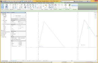
The goal is to produce the facets for a complex surface arranged neatly on a sheet for cutting, with each component numbered. Here is such an arrangement in Revit. To cut this on our laser cutters or CNC machines, I merely Export the Revit view in DWG format and adjust it slightly for layers for sending to the machine. The view is already scaled appropriately for the cutting bed.
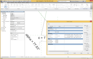
The concept is to regenerate the triangles in a separate file and lay them out neatly. A label object automatically provides the ID in panel, row, and column by getting values from parameters in each object.


The method is to generate the triangles using a Lookup table, which is basically a spreadsheet from Excel, describing the parameter values for all of the triangles. The flattened triangle is a family of category Generic Model that accesses the lookup table. Getting a triangle to configure properly given the two angles and side length was tricky, but eventually it fell into place.
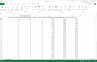
The lookup table must follow a very specific set of rules for its formatting. Each component is a record in a flat file database and is listed in a row, where each column describes a field. The first row is ignored, but can contain a test description of the item. The columns must have headers with a special syntax. The first part of the header is an identifier, the second part is the type of data (usually NUMBER), and the third part is the units, such as FEET or INCHES. These parts are separated by the special symbol ##. The table must be saved as a CSV file and then loaded into the family using the Manage Tables function.
When the Revit family accesses the table (I have stored the name of the table in a parameter “table”) it uses the size_lookup() function. The first argument is the name of the table. The second argument is a text string that matches the column in the table that contains the value to return. The third argument is a default value to return if the lookup action fails. The final columns contain values to look up in the table beginning in the second column of the table and moving sequentially across columns. In this example, the function looks for a match in the three columns of “panel”, “col”, and “row”.
 The lookup table was generated from the Revit model of the triangulated surface. The table is simply a schedule of the Generic Model objects that was saved as a CSV file (txt file extension). Schedules can only be made in Project files, so the project file contains the family that depicts the surface with its triangles. The CSV file was opened in Excel and pasted into the worksheet template.

A curtain panel pattern-based contains the triangles and was applied as a Divided Surface to the form.

The curtain panel pattern-based family uses a triangle pattern. It consists mostly of a triangle facet family that uses shared reporting parameters to collect the data for the schedule.
The system can be used to flatten anything that is planar and that can be parametrized.
We will cut some of these out in the next few days and see what we get.


Key to manufacturing curved surfaces that have been designed to be faceted is to lay out the facets on a single flat play for cutting, a process simply called “flattening” or “unfolding” or “developing”. The flattened arrangement can be arranged on a piece of panel stock and cut with a laser cutter, CNC router, CNC plasma cutter or other CNC equipment.


Typically flattening is done with AutoCAD (shown in my post from 8/Aug/2013, Fabricating Revit models: laser cutters) or Rhino’s Unrollsurf or Smash command. Here is a way to do it in Revit.
I haven’t had time to describe this, so I will show the process backwards, from the end result to the beginning. This will illustrate the concepts.
The goal is to produce the facets for a complex surface arranged neatly on a sheet for cutting, with each component numbered. Here is such an arrangement in Revit. To cut this on our laser cutters or CNC machines, I merely Export the Revit view in DWG format and adjust it slightly for layers for sending to the machine. The view is already scaled appropriately for the cutting bed.
The concept is to regenerate the triangles in a separate file and lay them out neatly. A label object automatically provides the ID in panel, row, and column by getting values from parameters in each object.


The method is to generate the triangles using a Lookup table, which is basically a spreadsheet from Excel, describing the parameter values for all of the triangles. The flattened triangle is a family of category Generic Model that accesses the lookup table. Getting a triangle to configure properly given the two angles and side length was tricky, but eventually it fell into place.

The lookup table must follow a very specific set of rules for its formatting. Each component is a record in a flat file database and is listed in a row, where each column describes a field. The first row is ignored, but can contain a test description of the item. The columns must have headers with a special syntax. The first part of the header is an identifier, the second part is the type of data (usually NUMBER), and the third part is the units, such as FEET or INCHES. These parts are separated by the special symbol ##. The table must be saved as a CSV file and then loaded into the family using the Manage Tables function.

When the Revit family accesses the table (I have stored the name of the table in a parameter “table”) it uses the size_lookup() function. The first argument is the name of the table. The second argument is a text string that matches the column in the table that contains the value to return. The third argument is a default value to return if the lookup action fails. The final columns contain values to look up in the table beginning in the second column of the table and moving sequentially across columns. In this example, the function looks for a match in the three columns of “panel”, “col”, and “row”.


A curtain panel pattern-based contains the triangles and was applied as a Divided Surface to the form.

The curtain panel pattern-based family uses a triangle pattern. It consists mostly of a triangle facet family that uses shared reporting parameters to collect the data for the schedule.
The system can be used to flatten anything that is planar and that can be parametrized.
We will cut some of these out in the next few days and see what we get.


Wednesday, October 14, 2015
11. Node connector. Designing curved architectural elements using Revit: Part 11
A node connector

A faceted surface has to be connected together and supported at the right location in space. This requires connectors. Node connectors are the most common way to do this, but they can be complicated because many panels come together at one point. Each panel requires a flat surface on the connector. Rotating the surface in multiple dimensions is complex.
One way to manufacture the complicated surfaces is by 3D printing the connector. In some cases, a design can be milled on a 3D router.
 The first step is to make a test surface. In the first variation, the connector will be a cylinder oriented to the surface with four flat surfaces for panels.
Apply a divided surface to it. For this first version, use a Rectangle pattern.
Create a New Family Generic Model Adaptive. Create five reference points with the first one in the center. The first one will locate the node, while the other four will connect to adjacent nodes to determine the surface angles.

Make the five points adaptive.
Zoom in on the Adaptive point 1. Set the Work Plane to be the horizontal plane. Make sure that Draw on Work Plane is selected. Draw a circle centered on this point.
Zoom in on the Adaptive point 1. Set the Work Plane to be the horizontal plane. Make sure that Draw on Work Plane is selected. Draw a circle centered on this point.

 Add a parameter to the radius of the circle. This can be a Type parameter so that it is easy to resize all of the connectors.

Select the circle and Create Form to make a cylinder. Lock the profiles and give it a Positive Offset value and a Negative Offset value.


The next step is to make void objects for cutting away shelves from the cylinder. To make it easier to see, I hid the cylinder while I worked on the next steps.


Draw Reference lines between the center point and the surrounding perimeter points.
Host a Reference Point on each of the radial arms.
Select a Reference Point and change its Measurement Type to Segment Length. Associate the property with a parameter and call it notch placement. This will determine the inner edge of the notch for a panel in the central cylindrical node.
Repeat this for each of the hosted points. You may have to change between End and Beginning values for the hosted points.
Draw lines between the hosted points. This will be an edge for extruding.


Draw additional lines to define a triangle where the panel will be. Select them, Create Form, Lock the profiles.
Repeat this step for the other panel shelves.


Select all of the panel shelves and make them into void forms.
Use the cut command to subtract the void objects from the cylinder.


Load the element into the test surface and place it on five nodes.
Use the Repeat command to propagate it across the surface.

Go back to the connector and Tab and click repeated to select the cylinder. Change its height.
Reload. This is better.


If we make it with a CNC 3 axis router, it might be faster and cheaper to manufacture. Making connector have a square base would facilitate manufacturing a lot of connectors and sawing them apart. Eliminating the ridges and walls would lead to less breakage.
Get out a new Generic Model Adaptive. This will be a connector for a hexagonal surface. Make a center node point surrounded by 6 vertex points.

Make them adaptive. Make sure the central one is Adaptive Point 1 and the surrounding ones are numbered clockwise.
Set the Adaptive Point 1 to Orients to Global (xyz). This will assure that its coordinate system always aligns with the Project file into which it is inserted. Mostly, we want the z axis to always go up.

Draw dimensions from the edge to the center plane to the edge, in both directions. Draw dimensions from the edge to the edge.
 Set the dimension strings to be EQ to make the square centered on the Adaptive Point 1. Label the overall dimension lines with a new parameter called size.
Select the square and Create Form to make an extrusion. Make sure that the profiles are locked, and set the Positive Offset to be 1” and the Negative Offset to be 1”.


A triangle pattern works better. The six panel connector can be placed on a surface divided with the triangle pattern to create a regular pattern.


This can be done by making the void objects with the blend tool instead of the extrusion.


Repeat with the other six points. Orient them by Insert (xyz) to make z the surface normal.


Pick each pair of chained lines and Create Form to make void objects.
Cut the solid connector with the void planes.
Test it by dragging the adaptive points around.
Reload into the test surface.


Subscribe to:
Posts (Atom)