Generating nodes
To make a surface buildable, it must be broken into sections
and a system for fabrication devised. After creating a surface, the surface
must be subdivided into nodes. Nodes are very important; they control how
elements are repeated across a surface using parametric variation. A node
defines the unique tangent plane at that point on the surface and the unique
surface normal. It carries with it a coordinate system and rotation of its xy
axes (the local z axis is the surface normal).
Revit provides three ways of making points on a surface:
divided surfaces (with patterns), intersects, and hosted points.
Before doing this part, you will need a surface. If you don’t
have a surface, the previous post describes how to make a surface for testing
and experimenting.

The divided surfaces are very easy to use. Simply select the
surface and pick the Divide surface button. It may be necessary to tap the Tab
key to get Revit to select the surface rather than a line.
A divided surface is a complex element. First, the Type
selector allows one to pick many different types of patterns, including rectangles,
triangles, brick patters, hexagons, and others. Second, the Surface
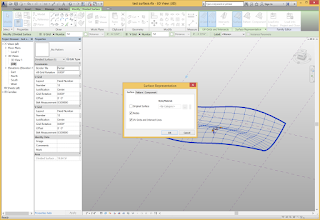
Representation panel extension allows one to control what is displayed. Use it
to turn on the nodes representation.
You can control the number of nodes on the U Grid and the V
grid. You can rotate the grid and offset it from the edge. The Layout option
allows one to control the spacing between nodes to be either a set dimension or
equidistant (fixed number).
A second way of making nodes is to use intersects. An
intersect is a reference plane that the user establishes. The divided surface
uses its own logic to create nodes. Often it defines nodes equidistant apart.
On a curved surface, this may not align with a grid line in plan view. Since architects
generally establish a grid for columns, alignment with the grid is important.
Intersects enable one to force that alignment.
To see the nodes created with intersects, set the divided
surface to have only 1 space on its U grid and 1 space on the V grid. These
will be along the edge of the surface.
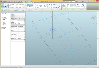
Use the Intersects tool and select reference planes to
intersect the surface. Reference planes must also intersect each other to
define a unique point on the surface. Use the check icon to finish your
selection. Turn nodes on to make sure that you can see the results.
An easy way to draw the intersecting vertical line is to
switch the work plane to be one of the vertical planes that is midway along the
surface. Draw the vertical line.
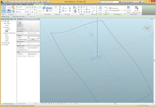
 Use the Point tool and draw a point on the vertical line.
Make sure that the Host on Face icon is active rather than the Host on Work
Plane. If done correctly, when you move the line the point will move with it.
Now select the point. A new option appears to Host Point By
Intersection. Choose this option and then select the surface.
 There is now a point at the intersection of the line and the
surface. If the shape of the surface changes or the location of the line
changes, the location of the point will change. Trying moving the line around
to see this behavior.
Once you have created nodes on the surface, it is possible
to start applying adaptive components to place themselves on the surface and
adapt their dimensions and geometry.


No comments:
Post a Comment