A facet
A curved surface can always be approximated by a faceted surface made of triangles. Other facet shapes can work, but are not guaranteed to work.The Buildz blog has some very informative stuff on these issues. Seehttp://buildz.blogspot.com/2012/05/repeat-and-divide-prt-i-curved-panels.html
Making triangle facets in Revit reveals some subtle points relating to the qualities of curved surfaces.The issue in constructing a faceted surface is that if the facets are tightly packed so that there is no space between facets, there is a risk that the thickness of the facets will cause physical clashes. The edges of the facets for a tightly packed arrangement must be chamfered at the correct angle. Fabrication of these chamfered angles requires a four axis milling machine or a 3D printer or some other special technique than simply a 3 axis milling machine. An alternative solution is to provide enough slack in the joints or intervening struts that can provide a tolerance.
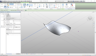
For good results in the computer model, this condition must be modeled. This exercise illustrates these issues and shows how to model both the chamfered edges and the tolerances in Revit.
The first step is to make or load a test surface. It is best to use a test surface that will have only a few facets, as the speed of producing the faceted surface is related to the number of facets. Also, you should plan for the test surface to have facets of about the size of your ultimate goal for facet size. Finally, the curvature should not be so excessive as to produce strange cases such as overlapping facets.
Points on the surface can provide the basis for faceting. Use the point tool and Place on Face setting to place some random points.
A prototypical facet can be modeled with a Generic Model Adaptive family. Place three points to define the corners, select them, and use the Make Adaptive button. Drag the points off the default work plane. This step helps to disambiguate what plane you are selecting.
Draw a Spline through points connecting each corner. An easy way to do this is to select two points and then pick the icon for Spline through points. Select the three lines, and use Create form to make a form, choosing the single surface rather than the extrusion.
Load the facet into the test surface. Place a facet on three of the points. You may find it easier if you set the Snap settings appropriately.
It may be easier to see the points if you turn on X-ray of the surface. Continue to place facets to get comfortable with the process.
If a facet is in the wrong place, it is generally easiest to simply delete it and place a new one. However, if you decide to move a point that already hosts facets, it is possible to hover over it and tap the Tab key until the point is highlighted. Then you can select it and drag it to a new location. Since it is hosted on the surface, the point will stay on the surface.
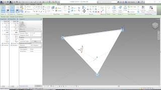
Moving the points allows you to control how accurately the surface is approximated.
These facets are infinitely thin, which of course is impossible to make in the real world. Thin sheet metal or paper is an approximation, but most architectural elements have discernible thickness.
To make a model of a real facet with thickness, go back to the facet family, select the surface and pick the Create form icon. This time, choose the extrusion option. Set the positive offset to something reasonable for fabrication, such as 1/2”.
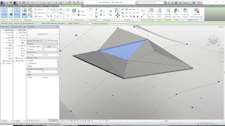
Reload the facet into the test surface. You may notice that some facets are extruded up and others are extruded down. This has to do with the order that you clicked the corners. You must click them all in either clockwise sequence or all in counter-clockwise sequence. You can delete facets that are wrong and place them again.
In my illustration, this looks great, but it is not. If I look at the model from underneath, the problem becomes more apparent. The facets are a confused mess of overlapping panels at the edges. If you fabricated these panels as drawn, they could not be assembled because the edges would overlap and interfere.
The solution is to realize that the panels should not be extrusions, but should be blends between an upper profile and a lower profile. Go back to the facet family and delete the form. You must offset a point from the tangent plane of the destination surface at each corner adaptive point. The horizontal plane at each adaptive point is the tangent plane. For each adaptive point, make this reference plane active and place a reference point on it. You can click through the warning that there are two points in the same place. Select one of the reference points and choose the Associate parameter button next to the Offset property. Add a new parameter, make it a Type parameter, and call it thickness.
Once this is set up, you can go into the Family Types dialog and change the offset property value. The reference points should move up and down.
Next, draw Spline through points through each of the three pairs of reference points.
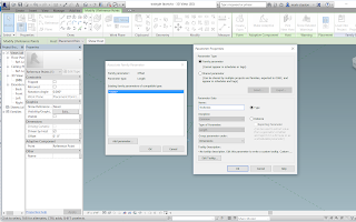
Now you can create a blend by selecting the lower chain of lines and the upper chain of lines and choosing the Create form icon. Although this looks the same as before, this time the upper points move as offsets from the tangent plane.
Load the new facet into the test surface to see what happens.
Depending on settings, it might be perfect or it might still be flawed. The issue is the coordinate system and orientation of the adaptive points. The correct setting is to set their orientation to be Host xyz. This means that they will take on the orientation of the surface at the location point. Once this is set, reload the facet back into the test surface. You should get a clean faceted surface, where each facet joins smoothly with its neighbors with a proper chamfer.
The other strategy for buildability is to undersize the facets by a tolerance factor. There will be deliberate gaps between facets, which in construction are typically filled with sealant, a gasket, or a mullion. The challenge in Revit is to construct lines parallel to the triangle edges but inside the triangle.
After saving the chamfered facet with a new name, delete the form. Delete the upper reference lines, because the facet with tolerances is designed to be a simple extrusion, cuttable on a 3 axis machine.
Set a work plane to be one of the lines. Draw a point on the line. It must host to the line, in which case it will change in display. You can snap to the midpoint of the line. Repeat this step for each line.
If you select the point, it has a property called “Normalized Curve Parameter”. This is a way of measuring along the line when, as a line controlled by adaptive points, it has no set length. The Normalized Curve Parameter at one end (the Beginning) has a value of 0, while at the other end (the End) it has a value of 1.0. At the midpoint, it has a value of 0.5. Make sure that each of the points hosted on the line is at the midpoint.
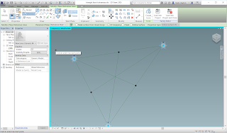
Next, from each vertex of the triangle draw a reference line to the opposite midpoint. You may recall from trigonometry that this line bisects the angle.
Place another point near the vertex on each of these angle bisectors. Select the point and look at its Property panel. You will see that there is a Property for Measurement Type. For the value of this Property, pull down the menu and pick Segment Length. This will allow you to specify a dimension along the line in feet and inches (or meters). Now there is a Segment Length parameter. Choose the Associate Parameter button and create a new tolerance parameter.
Repeat this step on the other two bisectors.
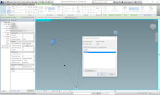
Now you have points that can be used to draw the inner triangle. Draw it using reference lines. Test it by changing the tolerance value and dragging the adaptive points around.
Once it is all working, select the inner triangle and Create form. You can set the thickness of the extrusion to be the thickness parameter created earlier.
Load this new family into the test surface. Try placing a few more facets to see how it works. Place them in the same order of rotation.
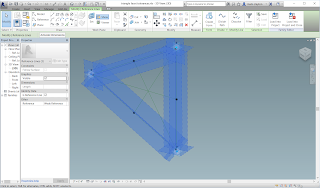
The final step is to measure the triangles for manufacturing. Another trigonometry fact is that a triangle can be defined as two lengths and one angle. We need to get the lengths of a and b and the angle between these two edges. Revit can report all of these numbers.
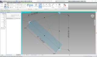 Back in the triangle facet family, hide the form so that the reference lines are visible. Use Set work plane on one of the lines of the inner triangle to make that the current work plane. Use the Aligned dimension on the two endpoints of the line to draw a dimension line. Repeat this on the other two lines of the inner triangle.
Test this by moving the Adaptive points up and down. The dimension lines should reorient in space and show the new length of each line.
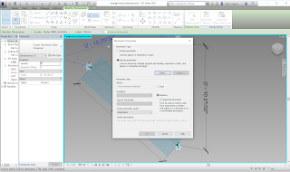
With one of the lines adjacent to the Adaptive point 1, select the dimension line and add a label, creating a new parameter. Make it an Instance parameter and click the Reporting parameter checkbox. Also make it a shared parameter.
Shared parameters are a way of using the same parameter definitions in many project files. They also have an important characteristic of being able to be listed in Schedules. A Schedule is a list of parameter values, such as a quantity survey. Shared parameters are defined in a separate file that is accessed by the multiple project files or family files.
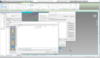
The first step is to make a Shared parameter file. Save it in a convenient location that you can find again.
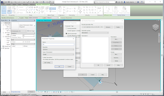
When you create a shared parameter, it must be assigned to a Group. So, one must create a Group before making any shared parameters. Once the Group is made, make a new parameter and call it a.
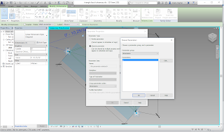 Close out the dialogs and assign a to the new parameter in the facet family.
Repeat the step for b.
In the facet family, make a new angular dimension between the two lines adjacent to vertex Adaptive point 1. Make this a shared parameter and name it alpha. Note that it must be an Angle type parameter.
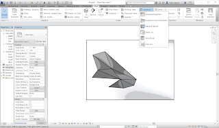
Schedules only exist in Project files. Create a new Project file and load the test surface into the project.
In the view menu, find Schedules and New Schedule/Quantities. A dialog will appear in which you tell Revit what category of objects you want to be in the Schedule. Choose Generic Model.
Next it will ask what parameters you want to appear in the schedule. These will appear as columns in your spreadsheet, while each instance will appear as a row. Choose Family/Type, a, b, and alpha.
You can reorder them by moving them up and down on the list. Choose OK and the schedule appears with all of the dimensions of the triangles
In a later post, I will explain how one can use the schedule of triangles to read back into Revit and layout a flat cut sheet. The basic idea is to use the schedule as a “lookup table” that is input to a triangle family. By incrementing the index of the triangle, the family uses the lookup table for each instance to determine its dimensions.


No comments:
Post a Comment