Tuesday, September 29, 2015

3. Ribbons and planks. Designing curved architectural elements using Revit, Part 3.

A ribbon using adaptive components


An ancient way of making a curved surface is to use planks. Boats and ships are built by nailing thin planks to bulkheads or ribs.

Modeling this in Revit is fairly easy using an adaptive component that works with the nodes on a surface.


Before one can do this, one must make a surface. Preceding tutorials describe how to do this. Create a divided surface with 6 divisions on the U grid and 6 divisions on the V grid.


Start a new file using Revit.New 
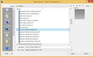
family. Choose Generic Model Adaptive. This modeling environment looks much like the Conceptual Mass modeling editor, but it has some different tools.

The adaptive elements are very strange. Dimensions are largely meaningless, as they can change when the object is placed. The geometry is controlled by adaptive points that are placed when the user places the component.

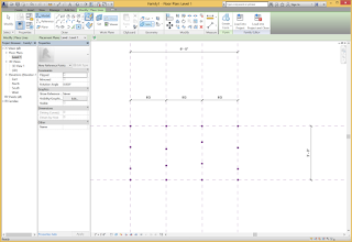
Using the point tool, place six points. They can be placed randomly, but I suggest that you put them into more or less a straight line.


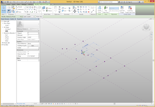
Now select the six points and pick the icon for Make adaptive. The points become numbered and show their coordinate systems. These coordinate systems will adapt to the location of the point, and settings on the point. The number of the point corresponds to the placement order of the point when the component is placed. The number can be changed.


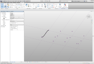
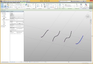
Select the six adaptive points and pick the Spline through points tool. You can twist and curve the spline by moving the points around in 3 dimensions.

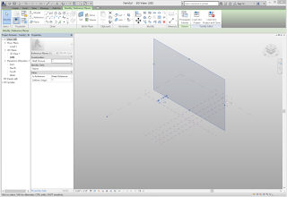
This line represents the length of the plank. You will sweep a shape along this line. The cross section of the plank must be drawn on a plane perpendicular to the line for sweeping. Use the Set work plane tool and carefully pick the plane on Point 1 that is perpendicular to the sweeping line. You may find it easier to move point 2 so that the plane is more distinct.


To make the adaptive ribbon, select the cross section and then CTRL select the path. You could drag across everything and then use the Filter command to select only the lines. Use the Create form tool to make the 3D solid ribbon.


You can drag the points around and the ribbon adapts. Save the ribbon.

Now it gets fun. Load the ribbon into your surface model. Using Load into project.
Place the ribbon on the six consecutive nodes of the surface.


Select the ribbon on the surface, and pick the Repeat tool. The ribbon gets repeated across the entire surface using six points at a time.


This ribbon isn’t quite right as a plank, but the cross section could be drawn more carefully and better results would occur. However, it should get the idea across.

The quantity of ribbons can be changed simply by changing the U and V grid numbers of the divided surface.


To build something like this, there are many physical constraints. The planks must both bend and twist, so the choice of material, thickness and width is important. Because our node generation was pretty sloppy, the planks might also be curved. There must be adequate ribs to hold the planks in the right location.


Experimentation with physical models may lead to an understanding of these constraints. Revit can be used to calculate the amount of twist and bend in each plank.


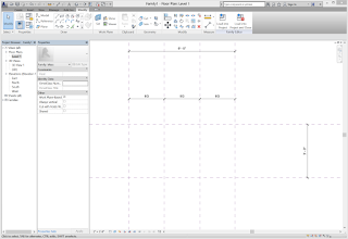
To draw the cross section, it is easy to use the Work plane viewer. Draw a narrow rectangle centered on the point 1. Dimension lines can help too. I made the plank cross section .25” x 2”.


2. Generating nodes. Designing curved architectural surfaces using Revit, Part 2.

Generating nodes

To make a surface buildable, it must be broken into sections and a system for fabrication devised. After creating a surface, the surface must be subdivided into nodes. Nodes are very important; they control how elements are repeated across a surface using parametric variation. A node defines the unique tangent plane at that point on the surface and the unique surface normal. It carries with it a coordinate system and rotation of its xy axes (the local z axis is the surface normal).

Revit provides three ways of making points on a surface: divided surfaces (with patterns), intersects, and hosted points.

Before doing this part, you will need a surface. If you don’t have a surface, the previous post describes how to make a surface for testing and experimenting.


The divided surfaces are very easy to use. Simply select the surface and pick the Divide surface button. It may be necessary to tap the Tab key to get Revit to select the surface rather than a line.

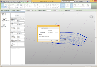
A divided surface is a complex element. First, the Type selector allows one to pick many different types of patterns, including rectangles, triangles, brick patters, hexagons, and others. Second, the Surface Representation panel extension allows one to control what is displayed. Use it to turn on the nodes representation.

You can control the number of nodes on the U Grid and the V grid. You can rotate the grid and offset it from the edge. The Layout option allows one to control the spacing between nodes to be either a set dimension or equidistant (fixed number).


A second way of making nodes is to use intersects. An intersect is a reference plane that the user establishes. The divided surface uses its own logic to create nodes. Often it defines nodes equidistant apart. On a curved surface, this may not align with a grid line in plan view. Since architects generally establish a grid for columns, alignment with the grid is important. Intersects enable one to force that alignment.

To see the nodes created with intersects, set the divided surface to have only 1 space on its U grid and 1 space on the V grid. These will be along the edge of the surface.


Use the Intersects tool and select reference planes to intersect the surface. Reference planes must also intersect each other to define a unique point on the surface. Use the check icon to finish your selection. Turn nodes on to make sure that you can see the results.


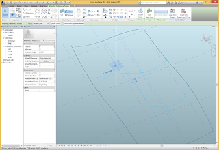
The final method (that I have discovered) for finding points on a surface that can be used in designing a structural system is to use a line that intersects the surface. This gives you complete and total control of the points used for structural support. However, it requires much more work. To experiment with this, draw a vertical line through the surface.

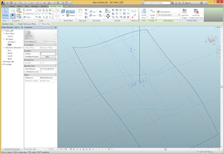
An easy way to draw the intersecting vertical line is to switch the work plane to be one of the vertical planes that is midway along the surface. Draw the vertical line.

Use the Point tool and draw a point on the vertical line. Make sure that the Host on Face icon is active rather than the Host on Work Plane. If done correctly, when you move the line the point will move with it.


Now select the point. A new option appears to Host Point By Intersection. Choose this option and then select the surface.


There is now a point at the intersection of the line and the surface. If the shape of the surface changes or the location of the line changes, the location of the point will change. Trying moving the line around to see this behavior.


Once you have created nodes on the surface, it is possible to start applying adaptive components to place themselves on the surface and adapt their dimensions and geometry. 

1. Test surface. Designing curved architectural elements using Revit, Part 1.

Part 1, A test surface

The first step is to create a test surface. The surface should not be too complicated, but should be sufficient to exercise a design thoroughly. A quick surface is made from a blended sweep with profiles placed on parallel vertical work planes.


Use Revit.New.Conceptual Mass to open a new family.

Controlling the location of points in 3D space is best done by creating reference planes for hosting elements. Viewing the 3D View, hold down the CTRL key and drag one of the vertical planes to make a copy vertical plane. The dashed blue line will appear when the copy is aligned with the original plane.Make two more vertical planes, for a total of four planes. Draw one vertical plane in the other direction.


In plan view, it is easy to add dimensions to the reference planes. I added a continuous dimension to the four parallel ones and set them to be Equal. I added another dimension to set the set of reference planes to be a total of 6 feet, and a dimension to set the other one to be 3 feet. 

It can be helpful to change the scale and zoom in close. 

In plan view, draw four points on each vertical plane.


Switch to 3D view. Play with the points by dragging them vertically. The blue arrow that appears when a point is selected constrains movement to be vertical.

Viewing in 3D can be challenging. A powerful tool is the View Wheel and its Center option. This sets the center point for the Orbit tool. It may also be helpful to set an appropriate scale.

Select four points on one vertical plane. This can be done by clicking each point while holding down the CTRL key, or window selecting the four points. Pick the Spline through points tool to create a spline curve through the four points. Repeat for the other sets of four points.


Select the four spline curves. Pick the Create form tool to make a surface. You can drag the points up and down to make the surface more interesting.

Save this file so it can be used in subsequent steps. 


0. Designing curved architectural elements using Revit. Overview of the tutorials.

Designing curved architectural elements using Revit

Complex buildings require complex models and complex modeling. Although doubly curved curtain walls have become a popular motif in contemporary architecture, they are not easy to design and model. This extended tutorial will go over several ideas for modeling a doubly curved surface and how the model can be represented using Revit. It consists of the following parts:

Part 1, A test surface
Part 2, Generating nodes
Part 3, A ribbon using adaptive components
Part 4, A facet
Part 5, A curved surface using a nine-point patch
Part 6, A curtain panel pattern based
Part 7, A brick
Part 8, A shingle       
Part 9, A strut
Part 10, An edge connector
Part 11, A vertex connector

Part 12, Examples

Or I may never finish this or change what I decide to post.