
Make some sketches first to figure out the shape and the geometry.
Bisecting the angle is a bit challenging. My method is to set points of a known dimension from the vertex along the edge of the triangle reference line.

Connecting the points on the edges adjacent to a vertex will
draw a line whose midpoint bisects the angle. Next, if I consider the known
dimension to be the length of the hypotenuse of a right triangle, I can use
trigonometry to calculate the length that midpoint is from the edge. I can use
the same technique to then calculate the location of a point on the edge that
defines a line perpendicular to the edge that also goes through the midpoint.
Along this line I can measure a given amount to define the width of the strut
that goes along the edge of the triangle.


In Revit, start with a new family based on a Curtain Panel
Pattern-based. Select the grid outer edge, and use the Type selector to change
it to a Traingle (flat). You can pull the points up and down to see the
triangle deflect in space.


With the triangle displaced in space, draw angular
dimensions between each two sides. It is important
that you dimension between the reference lines as they are controlled by the
adaptive points and can move freely in space. Label these dimensions with the
angle reporting parameters.
Label the angular dimensions with the reporting parameters
that you created.

 It can be convenient to select rapidly the plane defined by
the three vertices of the triangle. You can create a surface by picking the
three edges and clicking on the Create Form icon. Make just the surface and not
an extrusion.
It can be convenient to select rapidly the plane defined by
the three vertices of the triangle. You can create a surface by picking the
three edges and clicking on the Create Form icon. Make just the surface and not
an extrusion. 


The next step is to draw reference lines from each vertex
toward the middle of the triangle to bisect the angles.


Considering the first angle, place points on each adjacent
edge. Draw a reference line connecting the two points.


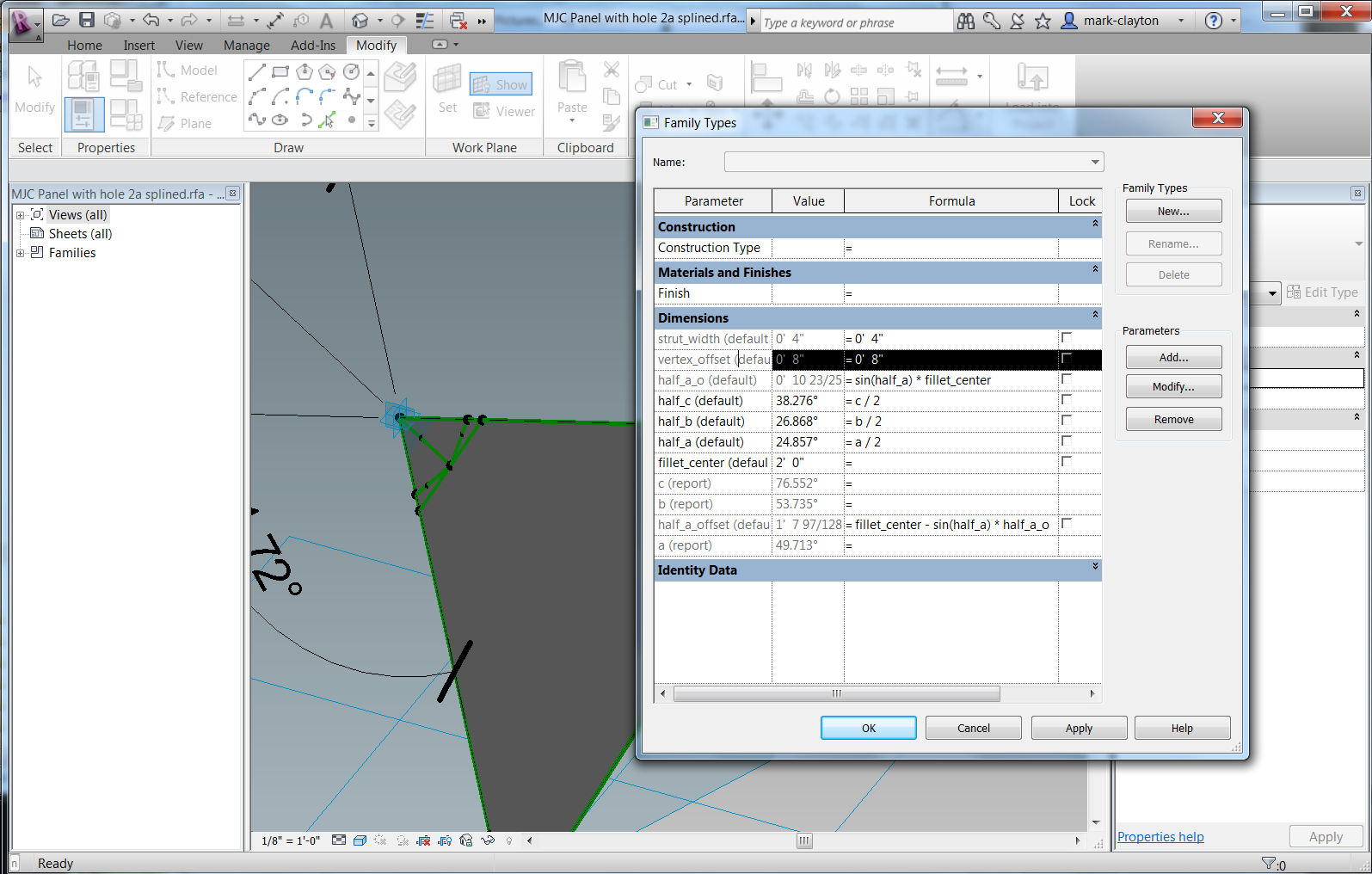
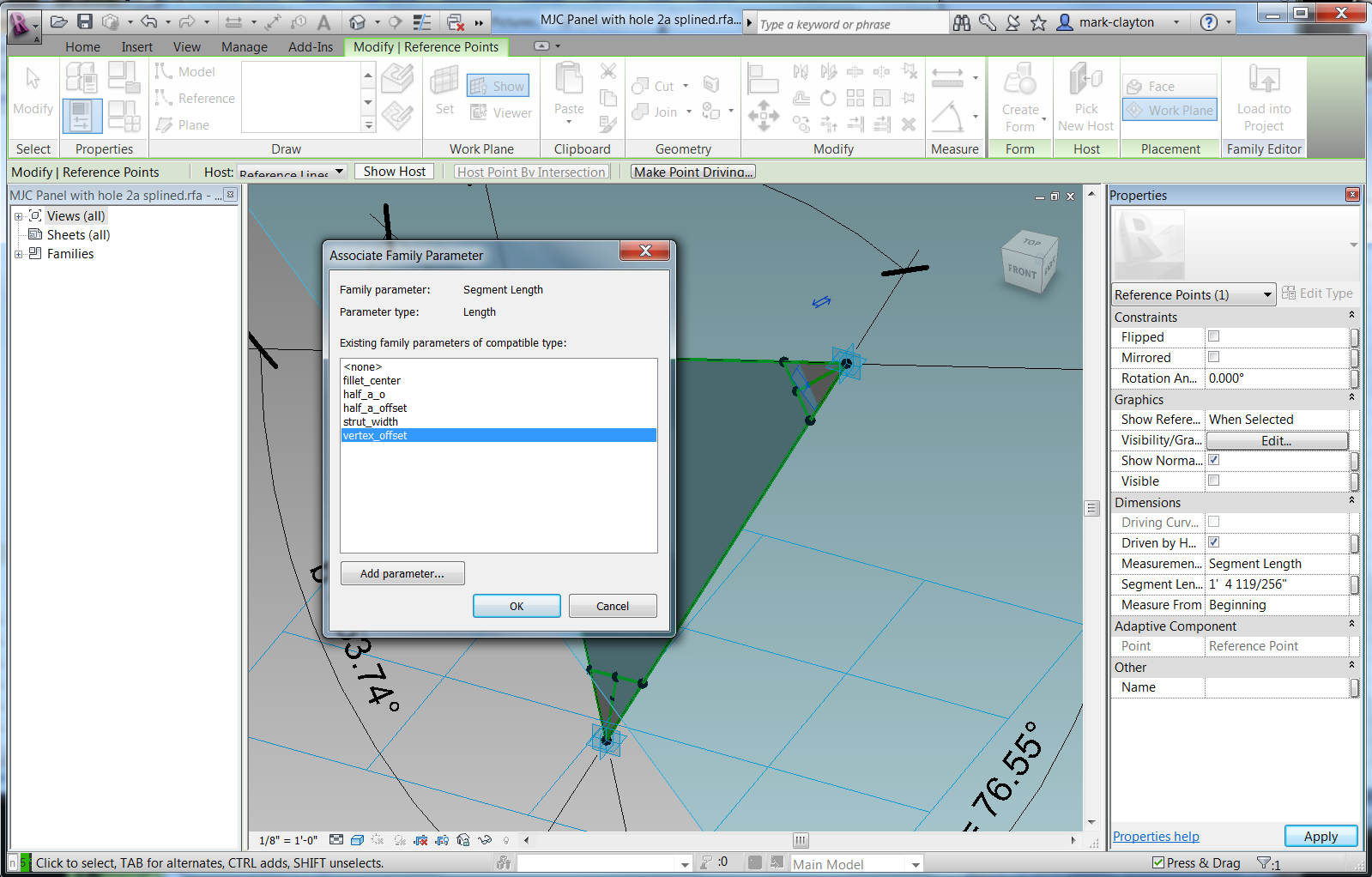
Click on the point and set its Measurement Type property to be Segment Length. Associate the fillet_center parameter with the location of the point, being careful to measure from the vertex by watching the blue arrows.

If you accidently set the Segment Length when the blue arrows are indicating the wrong direction, it seems best to set the association of the value to of the Segment Length to none, and then associate the value to the fillet_center parameter again with the proper direction.


The midpoint of the spanning line will be on the line that bisects the
angle.


Spin the model around and pull the adaptive points up and
down to make sure everything stays on the plane and the points and lines adapt
as they should.

The next step is to calculate the length along the edge of
the triangle that locates a line through the midpoint that is perpendicular to
the edge. This line will allow us to measure the thickness of the strut and the
endpoint of a curve that defines the fillet.


First, calculate the length from the midpoint of the base of
the isosceles triangle along the base to the edge. By the definition of sine, the
opposite edge equals the sin(phi) * hypotenuse. I created a parameter to hold
this value. Then I used this value to calculate another right angle length and
determined an offset from the vertex of the angle. Constructing a line from
this point back to the midpoint gives a perpendicular to the edge through the
midpoint.


A final control point determines the arc of the spline that
defines the fillet. This point must simply be on the bisecting line. I used a
parameter to determine how far the point is from the vertex.

Repeat this process to make six strut widths and three
control points for the fillets. Test the rig by moving the adaptive points up
and down.


Extrude the face that defines the panel. Make the hole into
a void object and use it to cut the panel.


Test it by loading it into a family or project and applying
it to a surface.This works better.


I like this panel. It could still be refined further, but its proportions seem elegant and it adapts well to the surface.
Is this Family available for Download? Very nice work.
ReplyDelete