Monday, January 18, 2010

The Case for Building Homes in Architectural Education

Introduction

In 2007, the Department of Architecture adopted a track focused on home architecture as one of three alternative paths to completion of the degree of Bachelor of Environmental Design. Under the curriculum devised at that time, students are provided with a broad suite of alternatives that include a traditional and conventional path in the Architectural Studies Track, an exploratory and self-directed path in the Research Track, and a construction-oriented path in the Home Architecture Track. While the Research Track largely consists of a customized degree plan of 13 credits in the senior year, the Home Architecture and Architectural Studies Track are based around studio sequences and integrated technical courses.

The Home Architecture Track consists of an eight credit experience in the fall semester and five credit studio in the spring semester. The fall unit combines ARCH 407 design studio with ARCH 432 and ARCH 436. The intention is that students will conduct a construction project at the Architecture Ranch and will gain hands-on experience with construction, structures, systems, detailed design, and project management. The spring semester consists of a final design studio (ARCH 408) that allows students to apply the practical skills that they have learned to produce innovative designs for homes that can then serve as plans for construction in the subsequent fall.

Motive

There are several motives for introducing the Home Architecture Track. The BED curriculum dates from the late 1960’s and is long overdue for a deep reexamination within the context of 21st century social needs and technological opportunities. The tri-partite form of the new curriculum allows the department to preserve the tried and true conventional sequence of courses while experimenting in new curricular forms. The Home Architecture Track is one of the experimental forms that has the potential to achieve a national and international reputation for excellence and help our department to establish itself as a leader. A minor consideration is the existence of the Mitchell endowment that provides funding and expects a commitment to residential design and construction.

Similar programs already exist at other schools throughout the United States. The Department of Energy Solar Decathlon Competition has been run through several cycles and has included up to 20 schools in each cycle. Several schools, such as University of Colorado, Virginia Tech, Cornell and Puerto Rico, have repeatedly participated in the competition, demonstrating a deep and strong commitment to home building. The list of participants is shown at http://www.solardecathlon.org/

Other schools have a commitment to home building independent of the Solar Decathlon competition. The University of Kansas has operated Studio 804 since 1995, building 14 projects of startling beauty. Auburn University is highly celebrated for its Rural Studio, which often involves building houses. The University of Kentucky has also built several houses under the leadership of Professor Greg Luhan, including the Resonance House, also seen in a video and the S.ky Blue House. The Yale building project was conceived at Yale University by Charles Moore, and has built houses for 40 years. Building houses in an architecture school has become a mainstream activity that is extremely attractive to students, former students, funding agencies, and the general public.

The regional context for Texas A&M establishes further motive. Hurricanes of recent years have devastated the housing stock in Texas, Louisiana, Mississippi, and Mexico coastal regions. The recent earthquake in Haiti is another example of the clear need in our region for disaster relief and provision of affordable houses to disadvantaged communities. As a land grant university, Texas A&M has a mission to provide service to the public and particularly the lower income residents of our region who have been harmed by these events. Recovery will take decades. Our department can seize the opportunity to lead recovery and serve the public in a very genuine and tangible way by helping to rebuild devastated communities and strengthen communities that are at risk.

In addition, the colonias of the border region have long been a focus for college research and service. These communities continue to have extreme needs to develop of residential resources.

Focus on innovation in residential architecture has strategic value for the department in two key areas. Green architecture and the concept of triple bottom line sustainability have come into strong focus as national and global priorities for current and future development. Global warming is a dominating issue of the 21st century (http://www.pewclimate.org/docUploads/Key-Scientific-Developments-Since-IPCC-4th-Assessment.pdf). The Intergovernmental Panel on Climate Change (IPCC) has identified decreasing energy consumption in buildings as the highest priority for immediate action in slowing the trend toward global warming and the reducing the impacts of climate change. Energy efficient residential architecture is a key part of surmounting the challenges that society faces from climate change. Texas A&M has an obligation to search for solutions to these problems. Demographic changes in Texas, the nation and the world are also a key driver for focusing on residential design innovation. Demand for housing and new residences will increase rapidly due to population increases, population migrations, disruptions due to environmental stress, and other factors. Texas A&M should provide leadership in finding solutions to the problems that will arise.

As compelling as these motives are, perhaps the most important motive for introducing the Home Architecture Track is the educational experience that it provides to students. Beyond the technical knowledge and skill obtained in architectural education, our department can provide experiences that are life-changing in the maturation of individuals that they offer. The Solar Decathlon effort that culminated in 2007 was a highlight life experience for those who participated. Students learned to work as a team, learned to accept responsibility, learned to provide leadership, learned to follow leadership, and learned how to achieve something bigger than the individual. They learned all of these within the context of architecture and construction. These are lessons that are at the core of behavior of a competent and successful architect. No other experience that our department can offer comes close to the experience of building a house in preparing a student be an architect and designer.

Resource requirements and availability

The Home Architecture Track will require reassignment of resources and generation of new resources, but should not adversely impact any other programs within the department. Personnel assignments, space allocations and funding availability are all needed.

The Home Architecture Track consists of 4 courses: ARCH 407, ARCH 408, ARCH 432, and ARCH 436. Accommodating one cadre of 16 students should require approximately 1 FTE at the typical teaching load of two courses per semester per faculty member. The skills required of faculty members probably suggest that the load should be spread over two or three faculty members. An efficient offering of the courses and the needs to achieve sufficient student-power to construct a house may more realistically require two sections of 16 students.

A willingness to redefine curricular content and expectations to accommodate the objective of building a house can lead to a relatively straightforward implementation of the track. The structures component should focus upon residential construction and structures, such as lightweight wood framing, wood joinery, slab-on-grade and simple foundations, SIP construction, cabinetry and fabrication. The systems component should focus upon residential systems, such as single zone mechanical systems, solar hot water, photovoltaics, simple water and sewage systems, home theaters and audiovisual design, and residential sustainable systems. Skills in these areas are typically within the expertise of architects, home designers and tradespeople rather than professional engineers.

Faculty assignments could be achieved as follows:
Fall Semester
ARCH 407-501, 16 students, Faculty 1
ARCH 407-502, 16 students, Faculty 2
ARCH 432-501, 32 students, Faculty 1 or Faculty 3

ARCH 436-501, 32 students, Faculty 2 or Faculty 4

Spring Semester
ARCH 408-501 Faculty 1
ARCH 408-502 Faculty 2

The fall semester staffing presents some challenges. A most efficient staffing would make use of two faculty members, one who combines expertise in design, structures and construction, and one who combines expertise in design and building systems. Alternatively, a specialist in structures and construction and a specialist in building systems could be assigned to work with two design instructors. Outside consultants in residential building technology could be provided to enhance the educational experience. For example, a contractor with expertise in photovoltaic system design and installation could provide a hands-on workshop, and be either uncompensated or provided with a stipend.

Graduate students, if carefully chosen, may be able to provide very tangible support through GAT positions. Risks are significant that the fall semester house building effort would be overly demanding of the time of a graduate student. It may be inadvisable to hire an M Arch student for this position as commitment to completion of the M Arch program should take precedence for that student. However, many of our PhD students have substantial experience in architectural practice or even building construction and could be of great support for the ARCH 407/432/436 sequence.

Another model for staffing could include hiring an expert from practice, either architectural practice or construction practice, to provide instruction and guidance during the fall semester. Funds from the Mitchell endowment could be devoted to this position.

Space needs are not exceptional. ARCH 407/432/436 can be taught in a normal studio setting with special activities at the Architecture Ranch for actual construction. If permission can be obtained, the sequence can be held entirely at the Ranch, relieving some demand upon space on the main campus during the fall semester, when demand is highest. ARCH 408 can be taught in a normal studio setting.

Funding for the house construction is probably the main barrier. However, informal conversations with students and former students suggest that building a house is an exciting and attractive prospect that could be funded through private donations. Cooperation from local builders and even regional and national builders is also highly probable. Contributions from material suppliers should also be achievable. A concentrated fund raising effort will be necessary to raise the funds. Mitchell funds can be used in the spring of 2010 to undertake a fund raising effort.
The Brazos Valley Affordable Housing Corporation has offered funds for building an affordable house (approximately $80,000). The house could be built at the Ranch and then moved to a lot for sale to a client. BVAHC suggests that it could be kept at the Ranch for up to a year to enable testing and monitoring before it is moved. Alternatively, our department could build the house on site or even design the house and provide plans to BVAHC for construction by them.

The funds needed for a meaningful experience are not overwhelming. Recently, the Auburn Rural Studio built a small house for $20,000. A goal of raising $100,000 in materials and cash contributions, coupled with funds from the BVAHC, should be adequate for a first prototype. This first prototype should be modest in size, use relatively conventional construction technology, and relatively conservative building systems. By setting our sights appropriately and avoiding high risk through too much experimentation, the program can get off to a solid start.

Benefits

In summary, the potential benefits are substantial while the costs are significant but not excessive. The primary benefit is an enhanced educational experience for the students who participate, increasing their confidence, leadership ability, and practical knowledge of architecture. An additional benefit is the public service provided by a continuing program of building affordable and prototype homes. The research benefits are also substantial, as we can use the homes as test beds for innovation in energy efficiency and sustainable design. The public relations benefit could be the most important value, as a continuing program can achieve national attention, attract support from agencies, inspire students and student applicants, and rally former students.

Recommendation

At this point, January 2010, the recommendation is to proceed with the Home Architecture Track by implementing the following steps:

  • Incorporate courses into the course schedule for Fall of 2010.
  • Conduct a competition to select a design for construction from the products of one or more studios in the spring of 2010.
  • Commit administrative leadership and resources at the department and college level to raise funds for construction of the first house.

The Home Architecture track can become a highlight of the Department of Architecture and help propel us to achievement of the consensus Top Ten position that is our stated goal.

Sunday, September 20, 2009

Strategies for fabricating curved surfaces

AutoCAD 2010 has very powerful mesh modeling tools, as well as the solid modeling tools that have been incorporated for many years. There are also tools for switching an object between the two paradigms.


With mesh modeling, you can create an object with multiple facets, edit the vertices, subdivide a facet into multiple facets, and control the smoothing. You can control how the mesh is applied to a solid, such as by using triangular faces or quadrilateral faces. Finally, you can explode a mesh into a collection of 3DFACE objects and use these entities to cut components on a laser cutter or CNC machine.


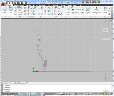
A starting point to explore these commands is to use the template for bulkheads that is described in the preceding blog entry. I suggest that you draw three or four profiles at equally spaced bulkheads. Draw them as closed polylines. You can then use the Loft command to make a "blob" shape. You should probably spin it around and look at it as well as you can. You may want to use the UNDO command to revert it to profiles and then edit the profiles to make a better shape.


You can use the Slice command from the solid editing tools to cut the back off and make it a flat vertical plane. You may also need to cut the bottom off so that it has a flat bottom.


There are several interesting things to do once you have a blob. You could use the Section command to make a series of polylines that could be cut on the CNC router to make plywood bulkheads. Once you make all of the sections, you can use "Align" to rotate them in space down onto a virtual piece of plywood. You can send that to the laser cutter or the CNC router. You could also cut horizontal sections parallel to the XY plane and have a two axis rectilinear plywood mesh.


To clad the blob, there are several strategies. You can use the plywood mesh sections to make a triangulated mesh by drawing the triangles using 3DFACE in conjunction with intersection snap. You could draw quadrilaterals in each section, but they won't necessarily align with the surface.
However, each quadrilateral can be folded to make two triangles. A bendable material, such as aluminum or sheet steel could be used to make patches. A pattern for the steel could be printed on the large format plotter and then each patch cut using tin-snips. Or the patches could be cut out of aluminum sheet on the CNC router, with a score line at the fold.


Another approach is to convert the blob into a Mesh object. The MESHOPTIONS command controls how it will be converted. It can be made up of triangles or "quads" of varying size and density. You can use the EXPLODE command once it is a mesh to generate 3DFACE objects. The faces can be ALIGNed with a virtual plywood for sending to the CNC machines. There are many variations of this approach.


A smooth surface can be created by making each patch on the 3D printer. This could be time consuming, but it is just machine time, and the end result could truly be beautiful. You can shell the surface into an 1/8 inch or 1/4 inch shell by using the THICKEN command and then chop it into manageable sized patches using the SLICE command. Stack six or eight patches up and print a stack all at once.


A rough surface can be created by using the idea of shingles. The shingles could all be the same size or they could vary in size and shape. The irregularity of the curved surface is accommodated by the overlap of the shingles.


Ruled surfaces are a simpler technique for a rather narrow type of curve. A ruled surface can be deformed out of a flat plane, such as a piece of cardboard or a sheet of plywood. Think of scoring the back of a cardboard piece so that you can bend it into a cone or a cylinder. AutoCAD has tools for making ruled surfaces, although unwrapping them is a challenge (other programs have commands for unwrapping a ruled surface.) Nevertheless, you could experiment with ruled surfaces and use the CNC to cut grooves in the back of a sheet of plywood so that it is easier to bend.


Try making at least one of these using the laser cutter. As you learn about the process it will become fun and exciting. The laser cut versions will teach you a lot about the detailing and challenges of making something bigger.

A template for making a blob in AutoCAD

Modeling with 3D CAD is pretty difficult even for those who are experience. I have overlooked how challenging it is for new students.

One of the key ideas for making CAD use easier is a very simple one but often overlooked. Derived from traditional methods of hand drafting, it is often extremely helpful to draw grids, layout lines, and set up other tools so that precision drawing is greatly facilitated.

I have set up an AutoCAD 2010 file that sets drawing units, limits, and the context for drawing a wall. Very importantly, the file establishes various User Coordinate Systems (UCS) that greatly aid drawing profiles and cutting sections through a shape once you make one. At one foot intervals along the length of the wall, there is a line along the y direction and a line along the z direction. These two lines provide object snap points by which you can draw section planes at these locations. There is also a UCS, named "bulkheadx" where x various from 01 to 26. You can go to the View menu and activate the UCS so that you can draw a profile that is oriented vertically at that bulkhead plane. By typing "plan" at the keyboard entry in AutoCAD you can even align the view with the UCS, making it very easy to draw a polyline or other entity to use for making a 3D object.


I actually used the Action Recorded in AutoCAD to partially automated the process of making the UCS at each bulkhead location. This is a very cool and powerful tool that could give you substantial scripting power.

You could use this template to draw each bulkhead of your wall as a polyline. You can use the DIVIDE command to add NODE objects at regularly spaced intervals along the polyline bulkheads. Or you could just be very careful about placing vertices of the polylines. Then you could draw another polyline connecting the various bulkheads like the stringers in the airplane models. These various polylines could be sent to the laser cutter or 3D printer to make a 3D grid.


You could put a surface on it by drawing 3DFACE triangles using the END point snap to vertices of the polylines. The ALIGN command will rotate them down onto a virtual sheet of plywood so that each triangle can be cut individually. Or you could place the triangles together into a strip and use the adjoining edges as fold joints. The strip could be plotted onto paper and then used as a full-size pattern for cutting metal to be folded.


The next blog entry describes some ways of further modeling a "blob" shape in AutoCAD and then dismantling it into buildable elements.

Tuesday, February 17, 2009

Double Trouble: AutoCAD solid modeling

Doubly curved surfaces are hard to imagine, hard to model, and hard to fabricate, but have become the signature of many "star" architects. AutoCAD is a great tool for making digital models of doubly curved surfaces and stripping them down into something that can be fabricated.

Many architects, particularly those who style themselves “designers”, know that it is a fact that AutoCAD is a necessary evil for drafting but is incapable of supporting form exploration.

They are wrong.

It puzzles me how they can cling to their ignorance. AutoCAD has incorporated a world-class 3D solid modeling system since the mid-1990’s. It uses the “constructive solid geometry” approach to modeling which depends upon operations such as extrude, revolve, sweep, loft, union, subtract and intersect to allow a designer to make very complex and sophisticated shapes.

I will identify the concepts and commands that AutoCAD accepts for making a doubly curved shape with arbitrary curvature. It’s easy, although a bit tedious. I will also describe how to use AutoCAD to disassemble the shape into planes that can be cut on a CNC router. Furthermore I will describe one approach to converting the shape into triangle faces that can also be cut on the router and assembled into a faceted construction of the original shape.

This is not a tutorial as the word has come to mean in the software industry. It does not describe each step, each click, each menu choice to complete the creation of a given form. Instead this blog entry describes the concepts and the AutoCAD commands that implement the concepts. If you want to make a shape sort of like the one that I illustrate, you can use the Help function to look up the commands and fool around until you get something you like.

The concept is to draw several profiles of the object that you want to make, ”loft” them into a 3D form, section them to make ribs and purlins, and apply triangular facets to define the form. This process only requires a few commands: PLINE, PEDIT, LOFT, SECTION, 3DFACE, and ALIGN. Other commands are essential but they are not distinctive, such as MOVE, VIEW, UCS, OSNAP.


The picture illustrates the process. You can see the profiles, stacked vertically. Next to it is the lofted solid object. The ribs and purlins make up a “waffle” grid. Finally, there is a 3D face on the waffle grid and another one rotated down onto the “floor”, ready to send to the CNC router.

If you are new to AutoCAD 3D, then the first step is to get very familiar with 3D viewing (very easy and intuitive in AutoCAD 2009) and the User Coordinate Systems (UCS). By default AutoCAD has a World Coordinate System that defines an origin and direction vectors for X, Y, and Z axes. The UCS command allows one to move, rotate, and align the working coordinate system to any position and orientation in the 3D space. You can also use the VIEW commands to quickly align views with the UCS to give you a plan view looking straight at the UCS. You can name and save a UCS for quick retrieval. These commands are absolutely critical to drawing in 3D space.

The first step is to draw profiles of the form that you want. I drew four closed polylines to represent the bottom face, two intermediate sections, and the top face of my wall. You can use the polyline command, the line command, the spline command, and pedit command to give you a lot of control over the profiles. I used the MOVE command to move the intermediate and top profiles vertically in space. You can use keyboard commands for moving or you can set your UCS to be a vertical plane such as an elevation and drag the profiles vertically.

The next step is to use the LOFT command to convert the profiles into a 3D solid. I suggest that you get out the Solid Modeling toolbars. Right click on any toolbar and pick the solid modeling, solid editing, UCS, and View toolbars. Before you use the LOFT command, I suggest making a copy of your profiles in 3D space. You may want to edit the profiles and compare multiple 3D forms. With the LOFT command, you pick each profile in order starting with the bottom one, and just accept the defaults. You can play with the different options and see how they change the form.

The SECTION command projects the solid onto whatever plane that you want. You will use it to make vertical ribs of your solid and horizontal purlins. I drew some layout lines to make it easy to find the planes for my sections using OSNAP settings. To get the horizontal sections, just use a vertical UCS. You can do it all in the 3D view which is kind of fun because you get to watch each section appear in 3D space.

Finally, the 3DFACE command allows you to apply triangular facets to the ribs and purlins using an intersection snap to get points exactly where the rib crosses the purlin. This gives you the complete model of the “virtual plywood” form. Its tedious, but, hey, you can make a few score faces in about half an hour. This sure beats manual drafting.

You can use the ALIGN command to rotate each facet onto the world coordinate system plane where you can arrange the facets, ribs, and purlins onto virtual sheets of 4x8 plywood. This is a really cool command but it is confusing to use. I’m not complaining – it is a complicated concept and the command is about as simple as it can be. Look at the Help function to see how it works.

Launch all of your virtual plywood off to the CNC router and you have the pieces to a faceted form that approximates the original doubly curved, lofted shape. Of course, since we did not design the joints or how to put it together it may be difficult to assemble it. If you laser cut it out of cardboard, then glue should be fine. I am working on several alternative joinery systems that will be easy to fabricate and easy to assemble.

Saturday, February 7, 2009

Wild forms with Autodesk Revit


Ok guys. I asked you to make cool, sexy, curvilinear shapes for train station canopies, studio furniture and houses. And, I want you to use Revit so that we can pull quantity take-offs, GBS anlayses, structural analysis and other evaluative studies off the central BIM. I did not know how to do that stuff, but I knew that we can figure it out. Here is my latest experiment.

The concept is to create a sweep or blended sweep in Revit as a mass family and use void objects to "crop" it into a smaller piece. You then use a "curtain system" to put grid of glass and mullions on it.

Create a New Family in Revit and choose the Mass template. Create a big "landscape" of a curved surface. Make it about 4 to 10 times the size of whatever you are designing. I was working on the canopy for the train station, so I made mine 400 feet by 100 feet. Start out with just a swept surface and don't make the profile or the sweep path too complicated.

It does not matter much how you derive the "landscape". You could use an actual landscape, such as the Brazos Valley, or you could just draw a random surface that looks cool. I am going to play with an extrusion of the form of the Mississippi River simply because the forms and ideas will remind me of my home town. The example pictures are a random surface.

Draw void objects in the mass family that you use to "cut" the landscape into a smaller piece. You make parameters for positioning the voids so that you can use the keyboard to move the voids around the landscape and crop different parts of the landscape away. I set mine up so that they measure from the origin of the mass family object. You can use the Family Types command and play with the parameters to make sure that they are working properly.

Once you save your mass, you can place it into a Project. You can tweak the parameters to shift the voids around to get a shape that you like.

In your Project file, use the curtain system object and attach it to the top face of the mass. The default curtain system has a 5'x10' grid which is way too big for my mass object, so I changed it to a 2'x2' grid. You will have to wait a few minutes, but it should generate an entire glass canopy structure over your mass surface.

You can edit the mass object by just changing the parameters. You will have to "remake" the curtain system but you can quickly try out another form for the canopy.

Here is a picture:

My example is pretty simple. There is one swept surface to create the "landscape". The clipping voids are rectangular boxes. You could create a positive surface out of multiple sweep objects, out of blends, or out of very complicated solid shapes. The clipping voids could be complex shapes themselves, such as curved extrusions, sweeps, cylinders or anything else. Finally, I used the defaul curtain system which is just a mullion and panel system. You could design a spider joint, or an overlapping shingle system, or even a welded steel shell.

Start simple and try it out. Slowly add complexity. Revit often supports substituting more complex elements for ones that you used to sketch an idea. For example, you can redo the Mass family and reload it into your Project to substitute a new form. You can build a new curtain system family and substitute it for the default one to get a new skin over your mass surface. I look forward to seeing what you do.

One more thing. I came up with this approach while trying to create structural ribs for a canopy system. It works very well for that purpose. You can place twenty copies of the mass family in the same location and then use the parameters to move the clipping planes at whatever rib spacing you want. The clipping planes can be set to be 4" apart, or 8" or whatever thickness that you want for the ribs. By making the ribs solid and then using the same mass form for the surface curtain system, you can make an entire structural canopy.

(Sorry that the images are so bad. My Revit files are way too big to upload and I am just learning blogspot. I may switch to a different way of sharing notes.)