AutoCAD 2010 has very powerful mesh modeling tools, as well as the solid modeling tools that have been incorporated for many years. There are also tools for switching an object between the two paradigms.
With mesh modeling, you can create an object with multiple facets, edit the vertices, subdivide a facet into multiple facets, and control the smoothing. You can control how the mesh is applied to a solid, such as by using triangular faces or quadrilateral faces. Finally, you can explode a mesh into a collection of 3DFACE objects and use these entities to cut components on a laser cutter or CNC machine.
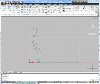
A starting point to explore these commands is to use the template for bulkheads that is described in the preceding blog entry. I suggest that you draw three or four profiles at equally spaced bulkheads. Draw them as closed polylines. You can then use the Loft command to make a "blob" shape. You should probably spin it around and look at it as well as you can. You may want to use the UNDO command to revert it to profiles and then edit the profiles to make a better shape.


You can use the Slice command from the solid editing tools to cut the back off and make it a flat vertical plane. You may also need to cut the bottom off so that it has a flat bottom.
There are several interesting things to do once you have a blob. You could use the Section command to make a series of polylines that could be cut on the CNC router to make plywood bulkheads. Once you make all of the sections, you can use "Align" to rotate them in space down onto a virtual piece of plywood. You can send that to the laser cutter or the CNC router. You could also cut horizontal sections parallel to the XY plane and have a two axis rectilinear plywood mesh.
To clad the blob, there are several strategies. You can use the plywood mesh sections to make a triangulated mesh by drawing the triangles using 3DFACE in conjunction with intersection snap. You could draw quadrilaterals in each section, but they won't necessarily align with the surface.
However, each quadrilateral can be folded to make two triangles. A bendable material, such as aluminum or sheet steel could be used to make patches. A pattern for the steel could be printed on the large format plotter and then each patch cut using tin-snips. Or the patches could be cut out of aluminum sheet on the CNC router, with a score line at the fold.
Another approach is to convert the blob into a Mesh object. The MESHOPTIONS command controls how it will be converted. It can be made up of triangles or "quads" of varying size and density. You can use the EXPLODE command once it is a mesh to generate 3DFACE objects. The faces can be ALIGNed with a virtual plywood for sending to the CNC machines. There are many variations of this approach.

A smooth surface can be created by making each patch on the 3D printer. This could be time consuming, but it is just machine time, and the end result could truly be beautiful. You can shell the surface into an 1/8 inch or 1/4 inch shell by using the THICKEN command and then chop it into manageable sized patches using the SLICE command. Stack six or eight patches up and print a stack all at once.
A rough surface can be created by using the idea of shingles. The shingles could all be the same size or they could vary in size and shape. The irregularity of the curved surface is accommodated by the overlap of the shingles.
Ruled surfaces are a simpler technique for a rather narrow type of curve. A ruled surface can be deformed out of a flat plane, such as a piece of cardboard or a sheet of plywood. Think of scoring the back of a cardboard piece so that you can bend it into a cone or a cylinder. AutoCAD has tools for making ruled surfaces, although unwrapping them is a challenge (other programs have commands for unwrapping a ruled surface.) Nevertheless, you could experiment with ruled surfaces and use the CNC to cut grooves in the back of a sheet of plywood so that it is easier to bend.

Try making at least one of these using the laser cutter. As you learn about the process it will become fun and exciting. The laser cut versions will teach you a lot about the detailing and challenges of making something bigger.