One of the key ideas for making CAD use easier is a very simple one but often overlooked. Derived from traditional methods of hand drafting, it is often extremely helpful to draw grids, layout lines, and set up other tools so that precision drawing is greatly facilitated.
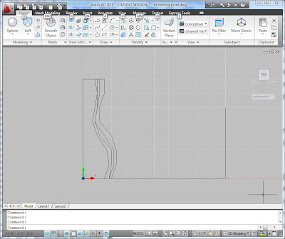
I have set up an AutoCAD 2010 file that sets drawing units, limits, and the context for drawing a wall. Very importantly, the file establishes various User Coordinate Systems (UCS) that greatly aid drawing profiles and cutting sections through a shape once you make one. At one foot intervals along the length of the wall, there is a line along the y direction and a line along the z direction. These two lines provide object snap points by which you can draw section planes at these locations. There is also a UCS, named "bulkheadx" where x various from 01 to 26. You can go to the View menu and activate the UCS so that you can draw a profile that is oriented vertically at that bulkhead plane. By typing "plan" at the keyboard entry in AutoCAD you can even align the view with the UCS, making it very easy to draw a polyline or other entity to use for making a 3D object.

I actually used the Action Recorded in AutoCAD to partially automated the process of making the UCS at each bulkhead location. This is a very cool and powerful tool that could give you substantial scripting power.
You could use this template to draw each bulkhead of your wall as a polyline. You can use the DIVIDE command to add NODE objects at regularly spaced intervals along the polyline bulkheads. Or you could just be very careful about placing vertices of the polylines. Then you could draw another polyline connecting the various bulkheads like the stringers in the airplane models. These various polylines could be sent to the laser cutter or 3D printer to make a 3D grid.
 You could put a surface on it by drawing 3DFACE triangles using the END point snap to vertices of the polylines. The ALIGN command will rotate them down onto a virtual sheet of plywood so that each triangle can be cut individually. Or you could place the triangles together into a strip and use the adjoining edges as fold joints. The strip could be plotted onto paper and then used as a full-size pattern for cutting metal to be folded.
The next blog entry describes some ways of further modeling a "blob" shape in AutoCAD and then dismantling it into buildable elements.
Texas Architecture And Miscellaneous University: A Template For Making A Blob In Autocad >>>>> Download Now
ReplyDelete>>>>> Download Full
Texas Architecture And Miscellaneous University: A Template For Making A Blob In Autocad >>>>> Download LINK
>>>>> Download Now
Texas Architecture And Miscellaneous University: A Template For Making A Blob In Autocad >>>>> Download Full
>>>>> Download LINK kR