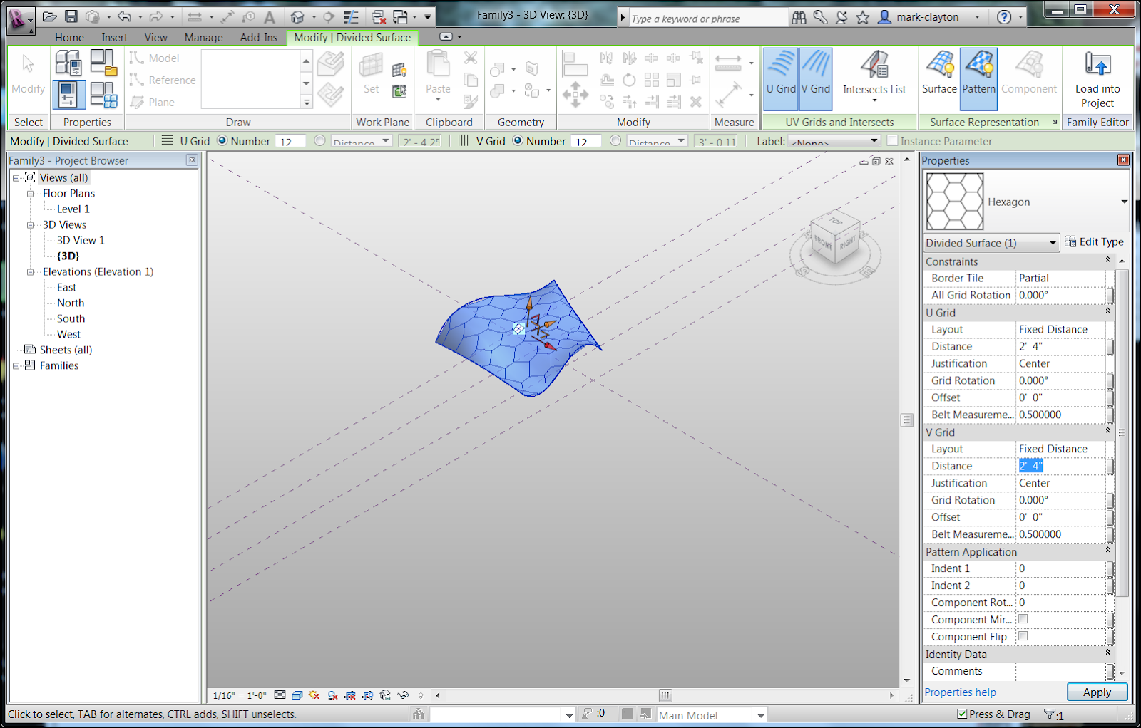
Making a field of flower-like shapes appears to be a challenge with Revit, but is a good exercise of how to make adaptive components and insert them into a pattern-based panel.
The first step is to plan the model. My approach is to make triangular petal object using the Generic Model Adaptive family template. This will be loaded and placed in a Pattern-based panel with a hexagon type, using mirrored pairs of petals This looks like a cloverleaf. This will be added to a divided surface defined using a Mass object. Good practice is to start simple and add complexity. Eventually I want the petal pairs to fold gently upward.
Petal
You must create an armature for constructing the shape of the petal. Think of this as scaffolding for construction. In the film industry, this is known as “rigging”.
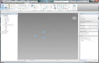
Upon opening the Generic Model Adaptive, create a triangle of adaptive
points. It does not matter where one draws the triangle, but it usually
helps to draw it approximately the size that you anticipate using in the
final.
Trace a chain of reference lines connecting the points to make a
triangle. Create a random set of point objects, and then use Pick New
Host to place them on the reference lines.
Construct additional
reference lines and host additional points on them to enable locations
for the control points of the curve that will make the petal.
You can test your rigging by selecting a
reference point on a line and changing the “Normalized Curve Parameter”
value. This is a number between 0 and 1 that locates a point on a curve
(or straight) line as a linear proportion along the length of the curve.
The reference lines should move and change without breaking or
separating from an endpoint.
Draw spline curves with control points on
the reference points that you created. You can move the curves around by
changing the Normalized Curve Parameter of the reference points.
The shape can be drawn all on the default workplane. When it is inserted, all points are going to be in the same plane.
I have not been particularly rigorous with controlling the curves in my
model. I suspect that there are cases that will cause the spline curves
to cross each other, which would create a chain that cannot be made into
an extrusion. Also, I have not controlled it to try to make sure that
the form is smooth. My shape has some abrupt changes, sometimes.
However, if you anticipate the size and shape of the final instances of
the flower, you can probably avoid failures.
Select all of the curves to determine a closed chain and extrude it. I
locked the top and bottom profile of the extrusion so that I don’t
accidentally modify it into a blend. This also gives positive and
negative offset values. Make the extrusion the thickness of the stock
that you will use to manufacture the panels. I set it for 1/2”. It would
probably be best to set it to .25” positive and .25” negative so that
it is centered on the insertion point, but I did not.
Cloverleaf
Next, make the pattern-based panel. Set the dimensions to be close to
those you expect to use in the final. Change it to a Hexagon.
Draw
crossing lines to construct the center of the hexagon.
Load your petal into the panel, and place a petal with the first of the
placement points at the center and the next two at the edge. I designed
my petal to have a straight edge between the first and second points,
allowing me to place petals in the hexagon in pairs that join along the
straight “fold” edge. Place the first petal in clockwise order, the
second in counterclockwise order, and so on. (This is why I should have
extruded it both positive and negative. In my model the petals don’t
line up perfectly because one in each pair extrudes up and the other
extrudes down.)
Flex the model by using a 3D view to drag the hexagon vertices up and down. The petals should deform to move up and down with each vertex independent.
Surface
Next, make a mass surface for arraying the petals. Open a New Mass.
CTRL click on the center plane to make additional vertical planes.
Click on a vertical plane to make it the active drawing surface and draw
a spline. Draw splines on each vertical plane. It is best to use the
same number of control points for each spline (although usually one or
two more control points doesn’t matter.)
Make the blended sweep by ctrl clicking all four splines and choose the Create Form icon.
Click the surface of the mass to select it. Choose the Divide Surface
icon. With the divided surface, choose the Hexagon pattern in the
Properties panel Type Selector. I changed the spacing of the divided
surface lines to be a fixed grid approximately the size of my final
design.
Switch views back to the cloverleaf panel. You can select the grid and
then use the button for Reset Points to Grid to move all of the flexed
control points back to the grid.
Load it into your mass.
In the mass, use the type selector of the divided surface to choose
your cloverleaf panel, wait a few moments, and the pattern is created on
the surface. It may fail for some of the panels when the angles are too
extreme. I suspect that mine failed for two panels that created a
self-intersecting curve that could not be extruded. I could either make
the mass surface a little more gentle or I could refine the design of
the panel so that it is more robust. I simply ignored the error by
clicking on Delete type.
Folding
The next step is to go back to the cloverleaf to make the petal pairs
curl up at the edges. The concept is to place reference points on the
adaptive control points and then move them up vertically. They must move
vertically in relation to the adaptive points and not the level
workplane. This means the reference points must be hosted by the
adaptive point.
Using the 3D view, place a reference point anywhere. Use the Pick New
Host to select the adaptive point that controls the corner of the petal.
Hover over the placed reference point and Tab until you can select the
reference point.
In its Properties panel, it has an Offset property. Change the value in
this property and the point should move vertically away from the
adaptive point. You can flex the model by spinning the 3D view and
changing the Offset to see the point move.
You can then select the instance of a petal to highlight it in blue. The
insertion points are then indicated. You can hover over an insertion
point and tab until you can select it. Move it up to snap to the offset
reference point. The petal should be “bent” upward.
(In this screen capture, I had deleted the petal, expecting to place it again with a snap to the offset reference point. This is not a necessary step because you can drag the insertion point of the already inserted petal to the new location hosted by the reference point.)
Reload the model into the mass to test the offset point.
If everything looks fine, go back to the cloverleaf family. Add
five more reference points in the same way. I arranged the reference
points so that there are two over the first adaptive point, two over the
third adaptive point, and two over the fifth adaptive point. These will
be the edges of the petals, while the spines of the petals go through
the second, fourth, and sixth points.
Make Parameters for the three offsets of the three petal pairs. This is
useful for controlling the petal pairs so that both edges go up the same
amount. I put in default values of 4”, 6”, and 8”.
Associate the appropriate offset parameter with the six reference
points. You should be able to control their vertical displacement by
changing the parameters.
Move the petal insertion points to snap to the appropriate reference
points. Flex the model by changing the parameter values and see the
petals fold up and down.
Reload into the mass surface. Again, there could be problems with one or
all of the cloverleafs. Try changing the size of the divided surface
grid to see if it will build at some size. Usually it will build at a
size close to the size of the hexagon grid in the cloverleaf.
Changing the fold dimension
Because we used parameters to control the offset, there is one
additional feature to exercise. If you click the divided grid, you can
then select an individual cloverleaf. In its Properties panel, the
offset parameters appear. You can fold the petal pairs upward by
changing these values. In this way, you can make even more complexity in
your form.
Breaking it
While everything looks great in my model, a few more trials show that
the cloverleaf is not robust -- it will break under some circumstances.
If the pattern is less than 1’7” it will not work. My guess is that the
curves become self-intersecting and cannot be extruded.
However, since I am able to make the design that I wanted, I will ignore the brittleness of the model.


 Upon opening the Generic Model Adaptive, create a triangle of adaptive
points. It does not matter where one draws the triangle, but it usually
helps to draw it approximately the size that you anticipate using in the
final.
Upon opening the Generic Model Adaptive, create a triangle of adaptive
points. It does not matter where one draws the triangle, but it usually
helps to draw it approximately the size that you anticipate using in the
final.