Moving Revit surfaces to a laser cutter
Laser cutters are a widely available tool that can make
possible models and structures of very complex surfaces. This post runs through
steps to cut a triangulated surface that was modeled in Revit. It uses Revit
and AutoCAD.
The laser cutter essentially moves a cutting laser along the
x and y axes like a knife blade. The intensity and speed of the laser must be
adjusted to cut through different materials. Since the laser produces high
heat, a material can catch on fire, so the settings must be correct given a
material and thickness. At low intensity, the laser can burn grooves, or etch
the surface.
Our laser cutter expects a cutting path defined as a
coplanar PLINE in AutoCAD. We use AutoCAD layers to designate the intensity of
the laser, either “cut” or “score”. The challenge is to move a set of panels modeled
in 3D space onto the cutting plane and change them from solids to PLINEs.
Exporting from Revit
Earlier posts describe most of the process, so this one is
largely review. A parametric triangulated, panelized surface is the starting
point (illustrated in the post on 2012/07/23). The first step is simply to move
to a 3D view of the surface in Revit and use the Export command to make a DWG
file (Figure 1). The view must be a 3D view to get a 3D model in AutoCAD. I used AutoCAD
2010 format because I have not yet updated AutoCAD to 2013. The process is
straightforward.
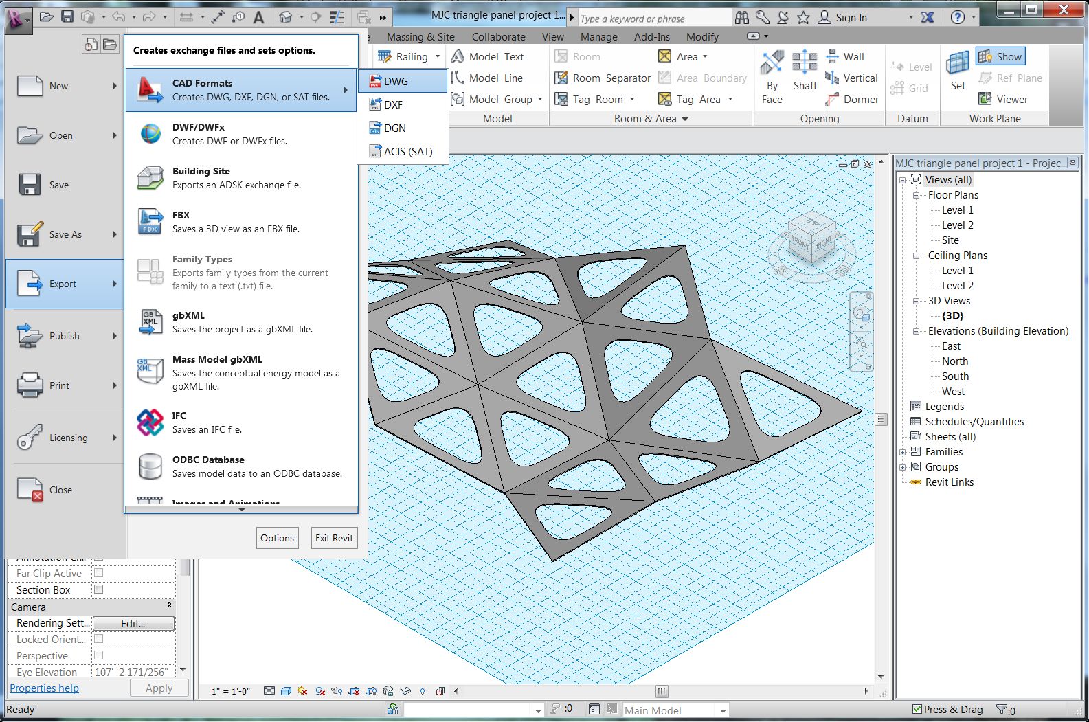 |
| Figure 1. |
That’s it for Revit.
Flattening the model in AutoCAD
I opened the file in AutoCAD. It appears in a 3D view that I
can spin and inspect. I notice that the panels are in 3D space and are tilted and
arranged to create the surface. Also, the panels are themselves 3D extrusions.
The following steps convert the panels to 2D objects and drops them onto the
cutting plane at z=0.
The key command is 3DALIGN (Figure 2). It is available from the
Modeling tool palette. Or just type in the command. The command will ask for 3
points defining XYZ axes on the element to be moved and then 3 points on the
plane to move to, effectively rotating the element in 3D space to align with a
new plane.
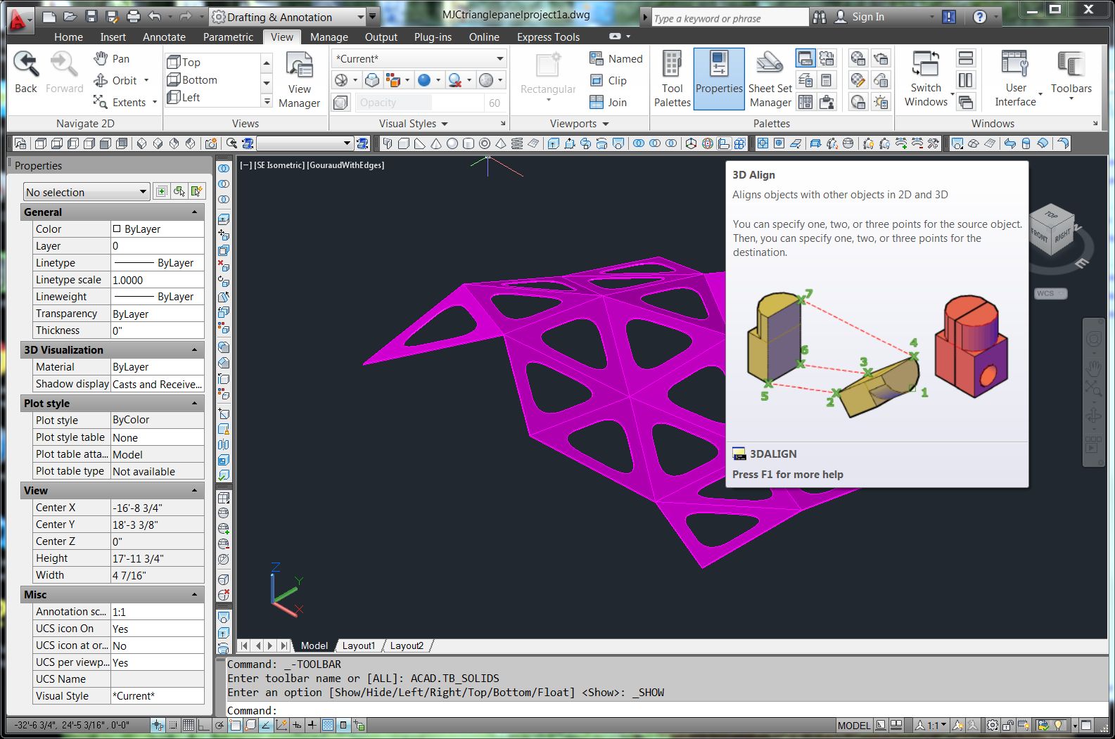 |
| Figure 2. |
When using 3D align, it is very important to be precise. The
panels are 3D objects with a top face, bottom face, and edge faces. It is
important to select the points in the right order to avoid flipping some
objects upside down. It is also important to snap exactly to points on the top face.
The other faces are unnecessary, so first they need to be deleted.
Converting the model to 2D objects
I will convert them to 2D objects by using the EXPLODE
command (Figure 3). Now, each triangle is a POLYFACE MESH (Figure 4). However, it is actually several
mesh objects to represent the top surface, the bottom surface, the outside edge
surfaces, and inside edge surfaces.
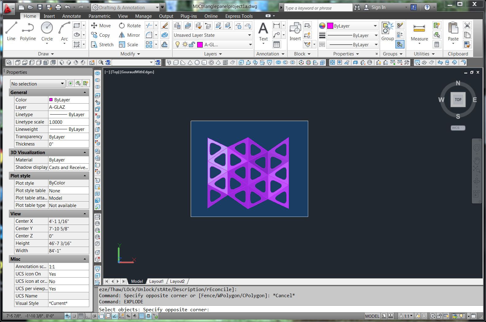 |
| Figure 3. |
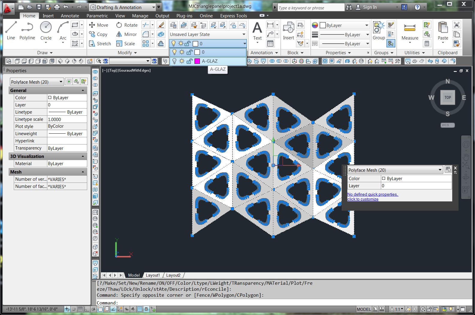
For laser cutting, I want only the top surface. The top
surfaces can be selected easily by clicking on the surface in a place that is
unambiguously the top surface. I changed the LAYER of these top surfaces to
LAYER 0 and then turned LAYER 0 to hidden (Figure 5). It is then easy to do a
window selection and delete the unneeded surfaces, with ERASE W command.
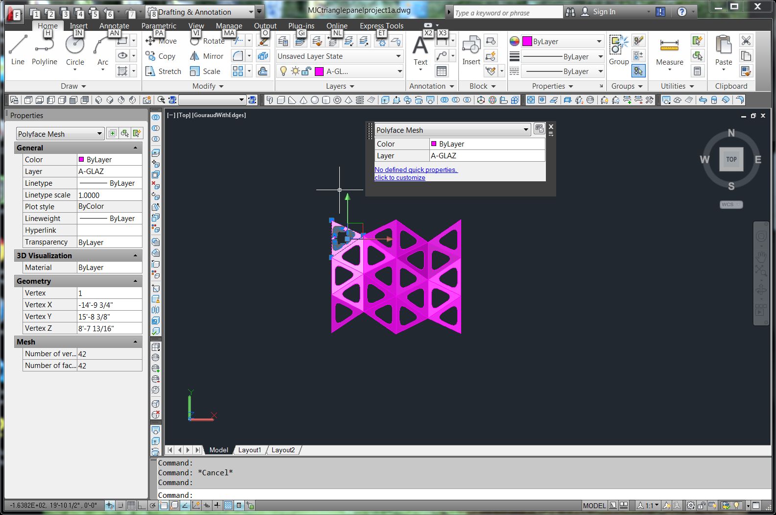 |
| Figure 4. |
The top faces can easily be moved back to the A-GLAZ layer.
Arranging the panels on the cutting surface
Before aligning the panels on the cutting plane, it is
helpful to create a grid on the cutting plane to locate the panels evenly and
provide some snap points. The Z=0 plane will serve as my cutting plane. I used
the LINE command to make lines from 0,20’ to 0,0 and 0,0 to 25’,0. The COPY
command can be used to make a grid of horizontal lines and then the vertical
lines (Figure 6). Doubling the vertical lines also gives more points to snap
to.
 |
| Figure 5. |
 |
| Figure 6. |
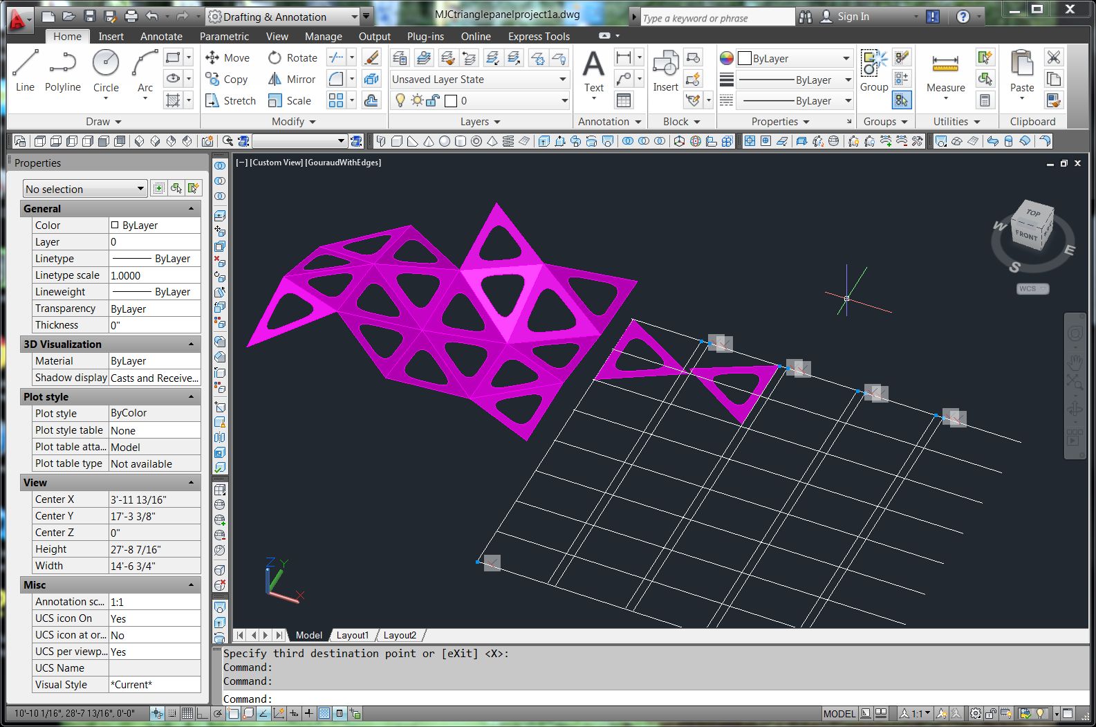
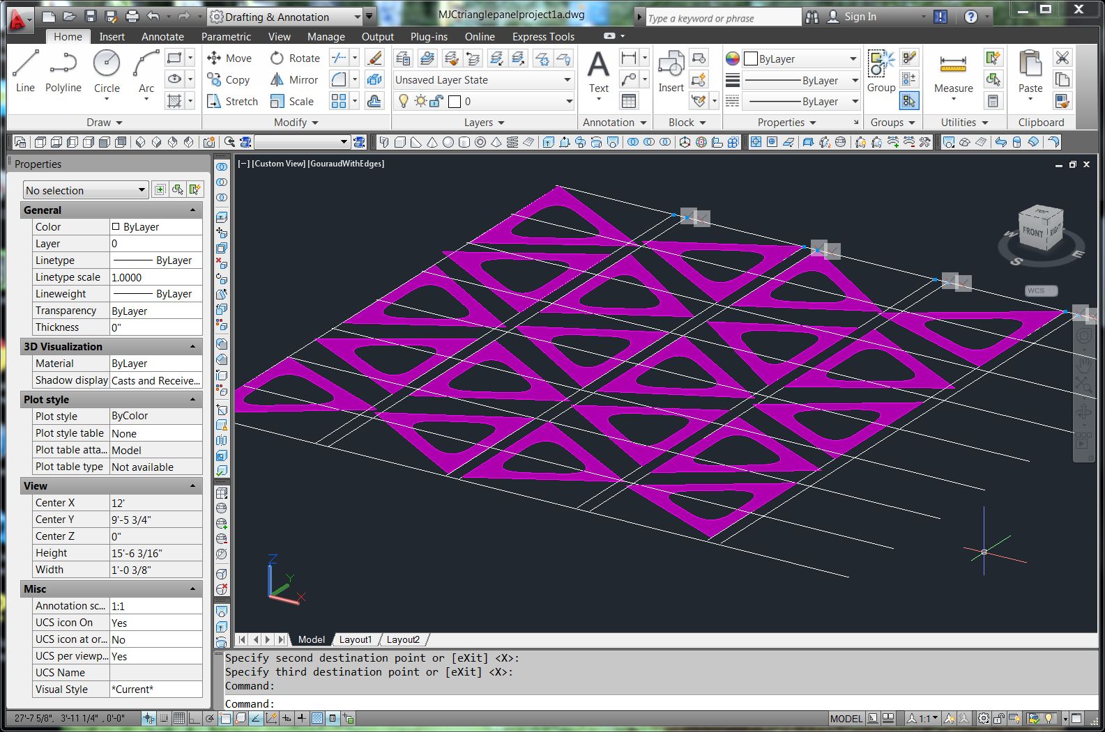
Use the 3DALIGN command to rotate the panels onto the
cutting plane. I enforced a consistent convention of clicking the top corner
first, the bottom corner second, and then finally the third point. In placing
the face, pick the points in the same order. This is important to keep the
faces oriented the same way as the originals. (Figure 7, 8).
 |
| Figure 7. |
 |
| Figure 8. |
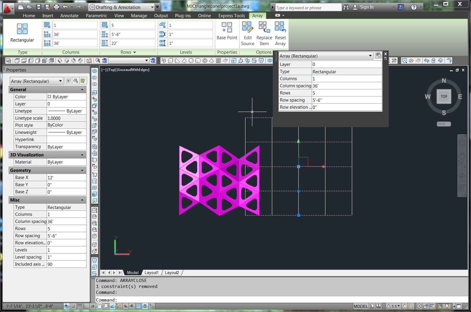
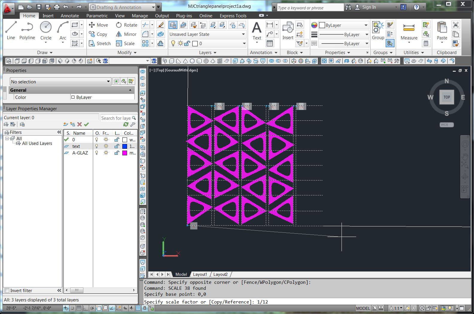
The panels must be scaled, labeled, and fit onto the cutting
sheets. For our lab’s laser cutters, I will scale them to 1:12. I selected all
of the panels and used the SCALE command (Figure 9).
 |
| Figure 9. |
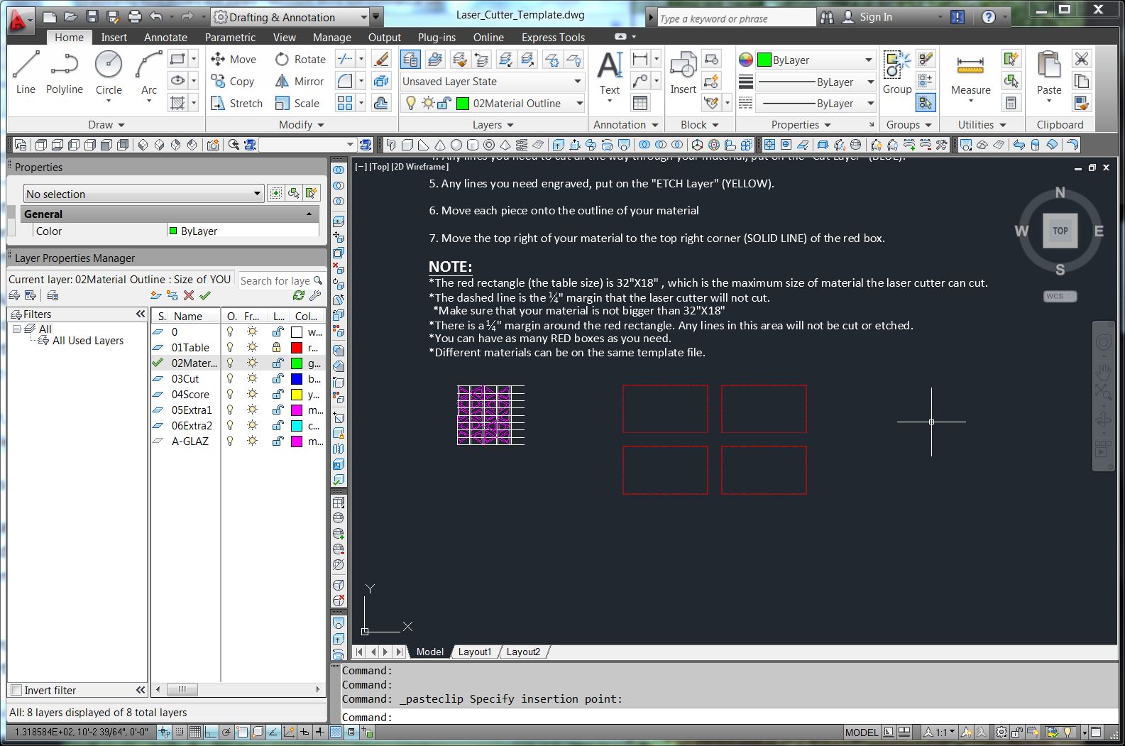
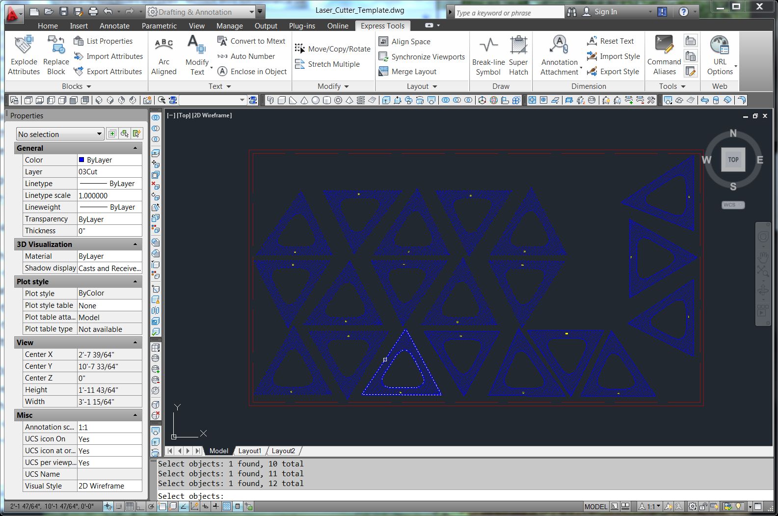
Our shop staff have created a template for the laser cutter
showing the bed size of the machine and assigning layers to the choices of CUT
or SCORE (etch). It is simple to open the template and then copy the triangular
faces and paste them into the template. The red lines designate the border and
margins of the cutting table (Figure 10).
 |
| Figure 10. |
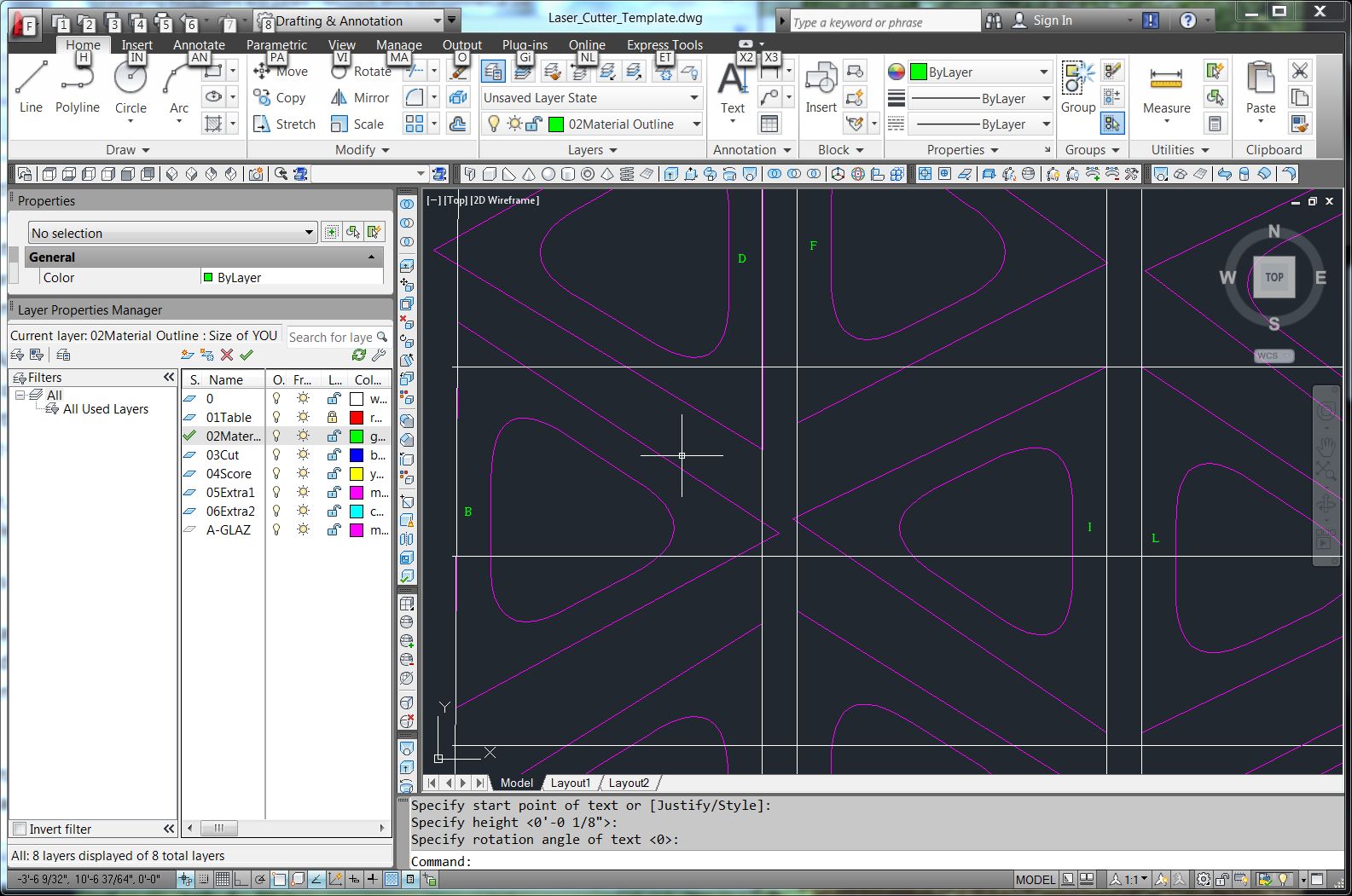
Labeling the panels
The next step is to label all the panels. Simply use the
TEXT tool (single line text) to add a letter to each panel. I put the text on a
separate layer (Figure 11).
I arranged the triangles on the cutting bed template, being
careful to keep them away from the margins. Care must be taken to retain the
labels. MOVE and ROTATE both can accept the Previous selection set, making it
easy to manipulate the correct panels. I deleted the grid lines because they
are no longer needed.
 |
| Figure 11. |
 |
| Figure 12. |
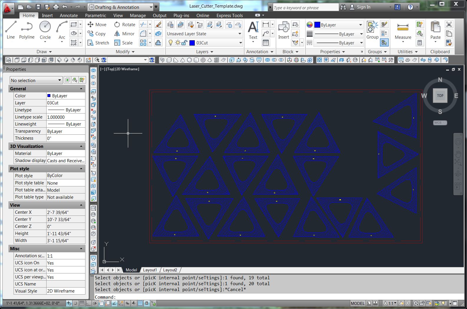
The last step is to move the elements to the correct layers
for the laser cutter. The panels were moved to the CUT layer and the text was
moved to the SCORE layer.
That is all that is needed in our shop.
A better model with tolearances
This model has some flaws. The panels are at the
mathematically exact size, not allowing for the material thickness that will
cause a clash with an adjacent panel. This does not matter if the panels are
cut from a very thin material, but if the material is more thick, they should
be undersized to allow for a tolerance. The best way to account for the
tolerance is to model it in Revit. However, it can be corrected in AutoCAD,
although the process is a bit clumsy.
First, the POLYFACE MESH objects must be converted into
PLINES. I can find no direct way to convert them; the EXPLODE command converts
a POLYFACE MESH to a 3D FACE, and that object cannot be exploded further. A
search on the Web reveals a clever work around of converting the POLYFACE MESH to
a BHATCH, deleting the MESH while retaining the BHATCH, and then regenerating
the BHATCH boundary as a PLINE.
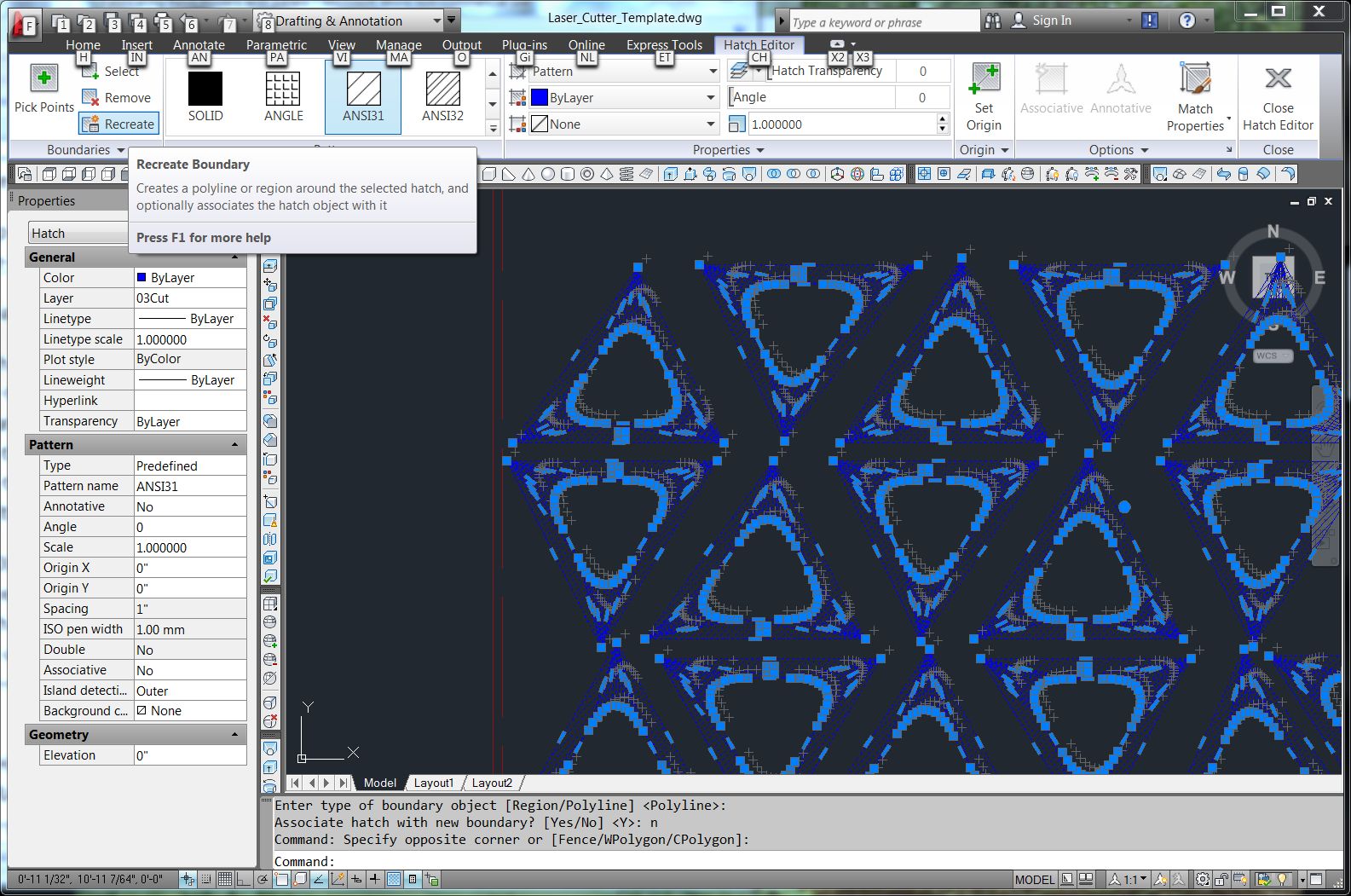
Using the BHATCH command, I picked each POLYFACE MESH to add
a hatch (Figure 12). Then using the ERASE command, I picked each POLYFACE MESH and erased
it, leaving the hatch (Figure 13). Then pick the hatch and use the RECREATE command to
produce a new POLYLINE around each panel (Figure 14). Next, delete the hatch elements.
 |
| Figure 13. |
 |
| Figure 14. |
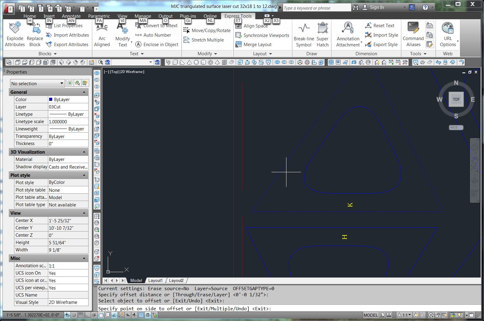
The last step is to create an assembly tolerance by making the
panels slightly smaller than as designed. This creates a tolerance that aids in
assembly. The idea behind this model is to tape the panels together. The tape
will cover up the gap between panels and enable them to rotate in space to the
correct position. I used the JOIN command to collect the three sides of each
triangle into a single PLINE, and then the OFFSET command to nudge the
triangles inward. I used a 1/32” offset. ERASE the original triangles (Figure 18).
 |
| Figure 18. |
 |
| Figure 19. |
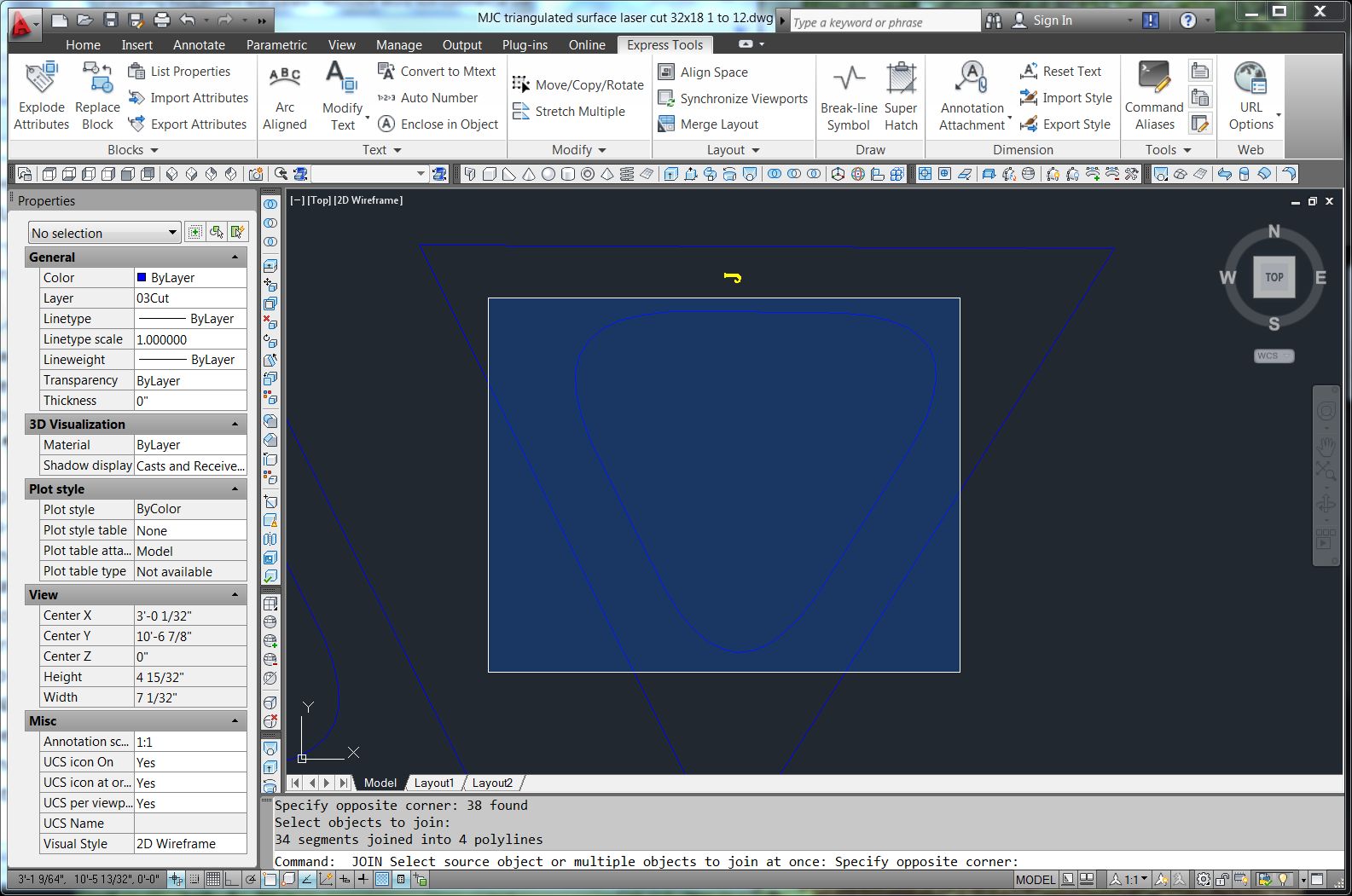
It is a good idea to JOIN the boundaries of the holes too,
as the laser cutter is likely to prefer a single PLINE rather than multiple
PLINES. Oddly, the JOIN command will not join all of the segments of a hole in
one operation, but if issued twice will join some of the segments and then the
rest of them. Careful use of a WINDOW selection (upper left to bottom right
window) can generally select all of the segments defining a hole at once. (Figure
19)
This is now a very good model that should present no
difficulties in cutting or assembly.


